Build FT Style F-18
Free plans and build log for building an FT-Style F-18 using Readi-Board or Ross foam core.

Build Goals
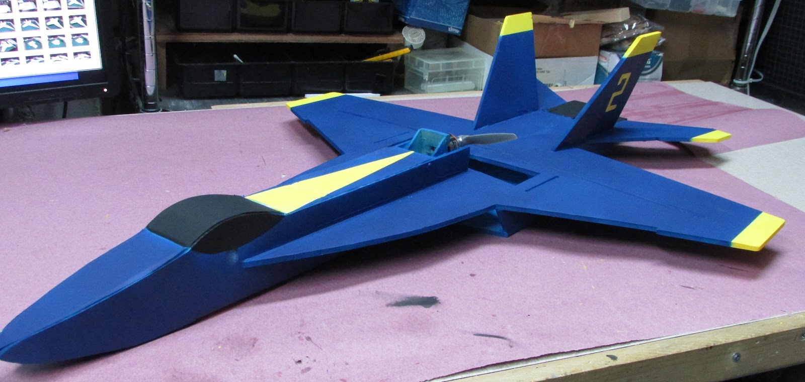
The goals of this build was to use a simple design familiar to FT builders which could be offered eventually as a speed build kit. The F-18 was designed to be the same size as FT-22 with a simple flat panel wing, 3 channel control and utilize construction techniques familiar to FT builders. By the end of this design and build process, I built a total of 4 planes, a prototype, and then versions 1 to 3. The last three versions used the same plans that provided at the end of the article. The differences between the versions are in the building materials (Readi-Board or Ross), motor, esc and battery size and then in v3, the addition of a carbon fiber tube for wing support. Since Ross is able to be painted without any preparation, version 2 and 3 sport the Blue Angels-like paint scheme.
F-18 Design Process
In order to create the pattern/plans, I first collected photos and some really great profile layouts from the internet. I'm pretty good with the computer, but it is still easier for me to print out a photo and draw on it with a pen to get the general idea of what parts are needed for a FT style aircraft.

Here are some of my thoughts after drawing an outline of the parts. The fuselage isn’t as wide as the prop hole needs to be - note that in the FT-22 the fuselage is way wider than “scale”. I would like to allow for 7” propeller, the same powertrain that is on the FT-22. However, if we use the size of the propeller hole to determine the width of the fuselage, then I calculated that the scaled wingspan would be 52” which is exactly twice the FT-22 at 26”. To make the F-18 with a 26” wingspan, we will need to widen the fuselage with respect to the wings. It turns out that an 8" prop hole aligns with the point where the leading edge wing extensions meets the wing. I think this is doable.
With these thoughts, I dropped profiled image into Adobe Illustrator and traced out the parts that I would need. It was a lot easier than I anticipated. In one evening I had printable plans (of some sort).

The above is the first design sketch I created in Illustrator. It was enough to cut out the basic shape.
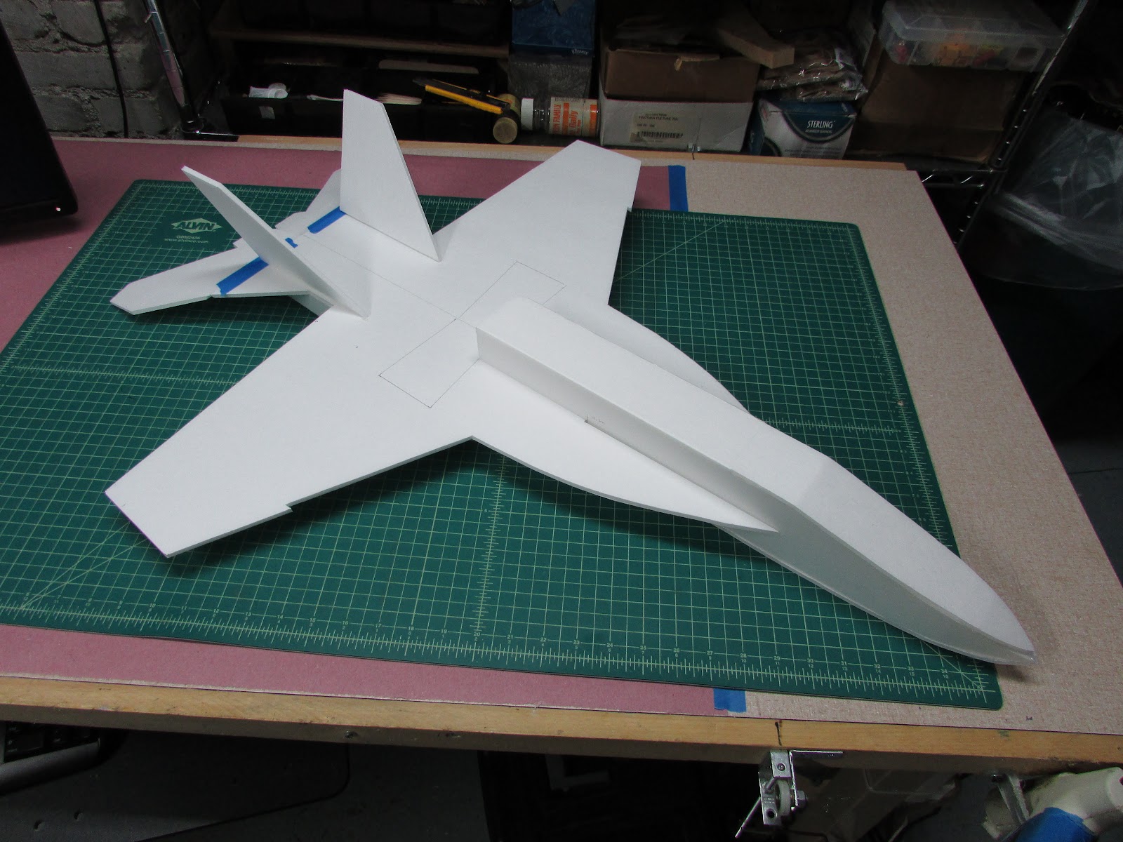
The prototype of the 26 inch wingspan plane was roughed out and does not have the cockpit.

The prototype allowed me to see if the plane would balance on the CG when I placed the electronics in the locations I would like them to go. The balance was perfect. The roughed out prototype also allowed me to how if the wings and fuselage would mesh and to fabricate different designs to the under the wing fuselage side panels could work. One kink in the fuselage - the tail is skinnier than the leading edge wing extensions, so the fuselage side panels under the wing will have to taper down or the tail will have to be widened.

From this prototype, you can probably tell that I designed the under-wing fuselage to be curved hourglass-like. I was also trying to get the engine intakes to be angled. After cutting them out several times, and playing with the bend angle, I finally succeeded, but it was a bit complicated, more complicated than you would want in a simple build. Another detractor for this shape is it is a restriction to the airflow, i.e. the tapered fuselage would trap a lot of air right behind the prop. I decided that to keep it simple and to come up with a "straight" design. We can put this curved design into the next more advanced or EDF build.
The prototype also allowed me to “feel” strength of the flat wing panels. They seem pretty fragile, but I am used to the strength of fiberglassed skinned foam core. In the end, we may need to add wing support like KF Airfoils (extra thickness of foam) or add carbon fiber tubes like other parkjet designs, but I’ll have to fly it in order to determine if it is needed.
Build the F-18 v1-3
The key to the plans is understanding the key, same as FT with the addition of creasing both sides of the foam core.
Black line - cut all the way through,
Red line - score cut, a cut through the top surface and through the foam but not through the bottom paper.
Blue lines are creases, Dotted for one side (away from plans) of the foam core and solid for the other (same side as plans).

Here is how the patterns can be laid on the 20”x30” foam core sheets. The plans that have the elevons connected to the wing panels will take three sheets of foam core (left) and the plans with detached elevons takes only two sheets of foam core (right). I will explain this later...
F-18 Plans with detached elevons
F-18 Plans with attached elevons
The plans have only one trace for each part, but for the build will require 2 of some parts, these are marked with “2x”. If you haven’t noticed, Readi-Board and Ross foam core have a little “natural” curve to them, at least most of the pieces I’ve purchased. For this reason, when cutting out the main wing panels, it is best if the curve of the board is oriented the same way on both pieces. Cut out one wing panel and then either flip the foam core over, or flip the plans over to cut your the other main wing panel. As a note, I did not do this on my first build and the curve was up on one wing and down on the other. As you can imagine, this puts a pretty stiff roll into the plane’s flight characteristics. I do not cut out the propeller hole until after the model is assembled. I poke holes through the plans and foam core to provide a location that will be cut later.

Tape the wing panels together with masking tape, put hot glue into the joint, hold flat on table and wipe of the excess glue. When cooled, remove the masking tape. Alternatively, you may choose to use any kind of tape you want and leave it affixed to the plane which adds strength to the joint.
Adding carbon fiber rod/tube to the F-18 wings (OPTIONAL and part of v3)
I recommend that you add a carbon fiber support to the wings. You will need 50 cm of carbon fiber tube/rod. I get mine at Radical RC. The length of 50 cm was chosen so that a one meter piece is enough for 2 planes.
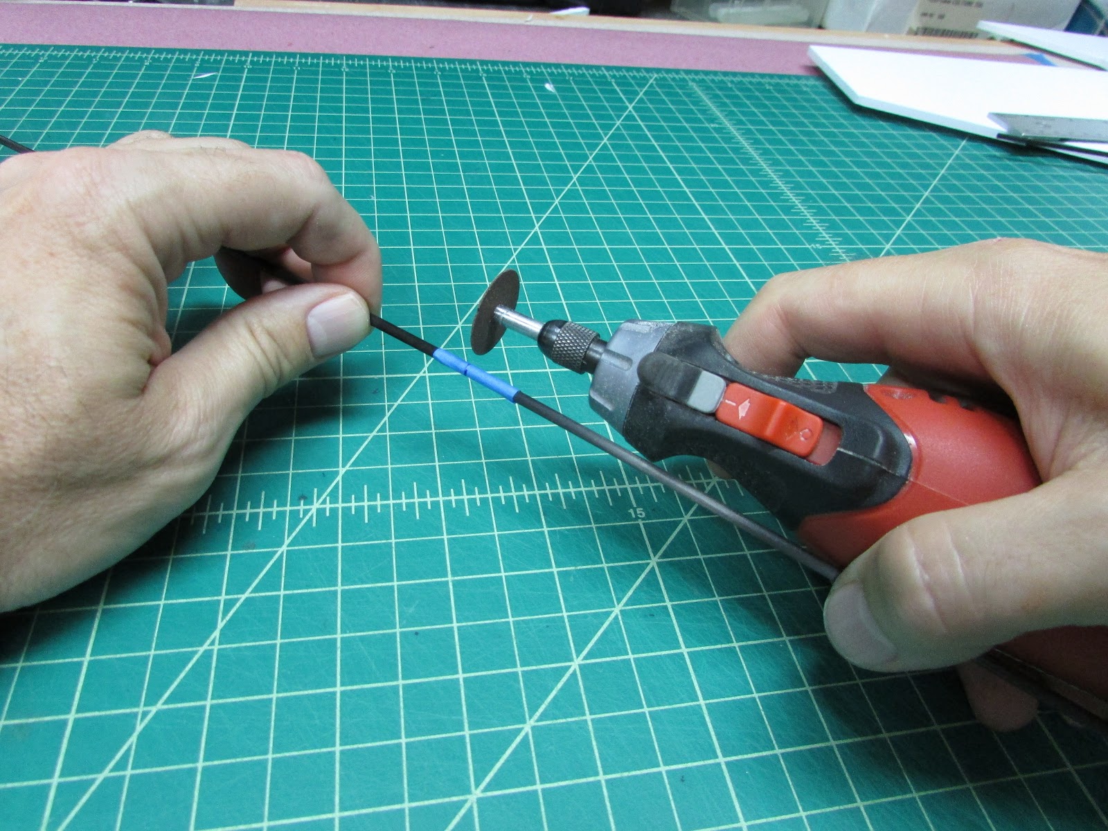
Cut using a rotary cutting tool, wrap the tube/rod in tape to prevent splintering and cut completely around the periphery before cutting through (use eye protection and dust mask).

Make two score cuts about 2 mm apart from each other where you would like the carbon tube/rod to be placed (this is mapped on the plans as a dotted score cut). You will want to remove just enough foam to fit the carbon fiber tube into a slot. One option is to use a hobby knife and cut two angled cuts and remove a “V” cut in the foam below the two score cuts. The foam peels out leaving a trough.

Drag the end of the carbon fiber tube/rod along the trough to shape it to the same size as the carbon fiber tube/rod.

Lay the carbon fiber rod/tube into the slot you’ve made to make sure it fits.
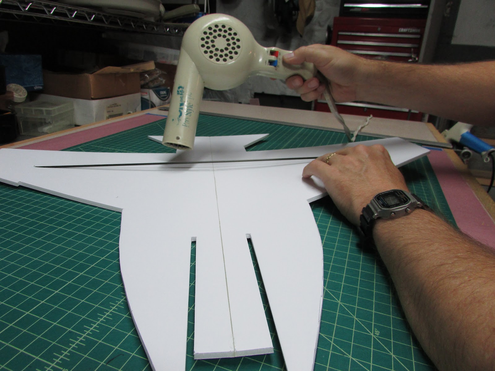
Warm the trough and the carbon fiber tube/rod with a hair dryer. Note that warming the foam core shrinks the paper on the foam causing it to bend. When it cools, it will be straighten out - just be sure to hold it flat while cooling. I chose to put my carbon fiber tube on the top, but it could have just as easily been put on the bottom side. Run a bead of hot glue the length of the slot, lay the warmed tube/rod into place and press it into the slot with a stick or piece of carbon fiber tube/rod. After it is completely seated, remove excess hot glue with an extra piece of foam and hold it flat. If you have a problem only get half way through the process and the glue cools, just use the hair dryer to warm the whole section up and keep pressing it in.
Building the fuselage
Cut out the fuselage pieces. I do not cut the wing slot in the rear until after it is glued together.

Crease the inside tips of the fuselage where you want to have it bend.
Glue the fuselage together B fold. If you properly creased the foam core, the nose will bend together into a point.

The two sides and the bottom of the nosecone are joined by running a bead of hot glue along both edges of the bottom piece, holding it in place and then squeezing the side pieces to it. While the glue is cooling, move the pieces around to get a nice fit.
Adding the fuselage top piece requires a bit of preparation.

Bend the foam core along the crease lines so that it roughly matches the outline of the fuselage. Glue the top piece of the fuselage to the sides by running a bead of glue along both sides of the top piece from the nose to the start of the cockpit. With the glue applied, place it between the side pieces slightly back from where it needs to go and slide it into place. Hold it while the glue cools.

The cockpit should be able to bend up at the crease where it meets the nose cone.

Run more hot glue on the sides of the cockpit and hold it in place. Then glue the little piece behind the cockpit. It should be like this when you are done. Don’t glue the battery hatch.
Cut out the slots on the side where the wing panel slides in. Draw a line that extends the bottom cut to mid way through the cockpit. This line will be used to align the leading edge wing extensions. Lay this piece aside while we finish preparing the wing panels.

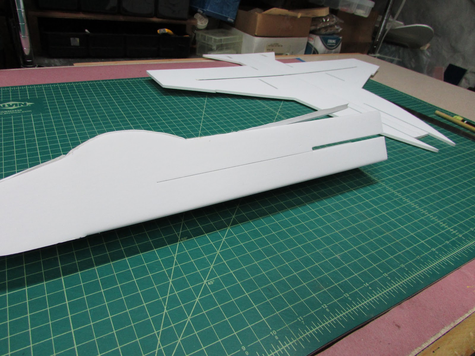
There are two offset and overlapping fuselage engine side panels in the “straight” design. The inside fuselage pieces (shown above) extend from the tail to the propeller hole. There are two tabs, one that fits into the double wide tab hole near the rear and the other lays along the flat section between the wing and the tail. The tab needs to be glued to the outside of the doublewide tab hole (rear tab) to leave room for the vertical stabilizers.
Now it is time to join the wing panels with the fuselage. Slide the wing panels into the fuselage piece. Make sure the front of the leading edge wing extensions align with the alignment marks you drew on the fuselage. Glue the wing to the fuselage by running a bead of glue along the seams and squeegee off the excess with a piece of foam. Glue both the top and bottom seams from the rear of the fuselage to the front of the leading edge wing extensions. Then open the battery hatch and glue the battery tray inside the fuselage to the fuselage wall and wipe off the excess glue.
It is easiest to attach the elevon panels, motor, ESC, receiver and servos before the belly plate is glued. They can be added after, but I found it easier to work on a wide open plane.
At this point I realized that the FT designs/plans have the control surfaces attached with paper and the original drawings had separate parts. I altered the plans that I originally made to attach the elevons to the wing panels. The downside to this plan is that it now takes three sheets to cut out the plane. No big deal… I’ve included both plans. If you want to use only 2 sheets of foam core, then you will have to attach the elevons using tape or hinges.

Because the Readi-Board paper peels from the foam so easily, on all my builds I would completely detach the control surfaces and connect them using polyester fabric and hot glue. That is why all the pictures above don’t have the elevon control surfaces attached to the wing panels. To proceed, you will need to bevel the elevons or bevel them and connect them using your favorite hinge technique. I’ve used tape and polyester fabric/hot glue and both seems to work fine.

Glue the motor mount in between the fuselage panels. I glue two pieces of foam core between the motor mount and sides of the fuselage to help align it. Cut a hole in the wing panel below the motor for the three motor wires to pass to the lower level.
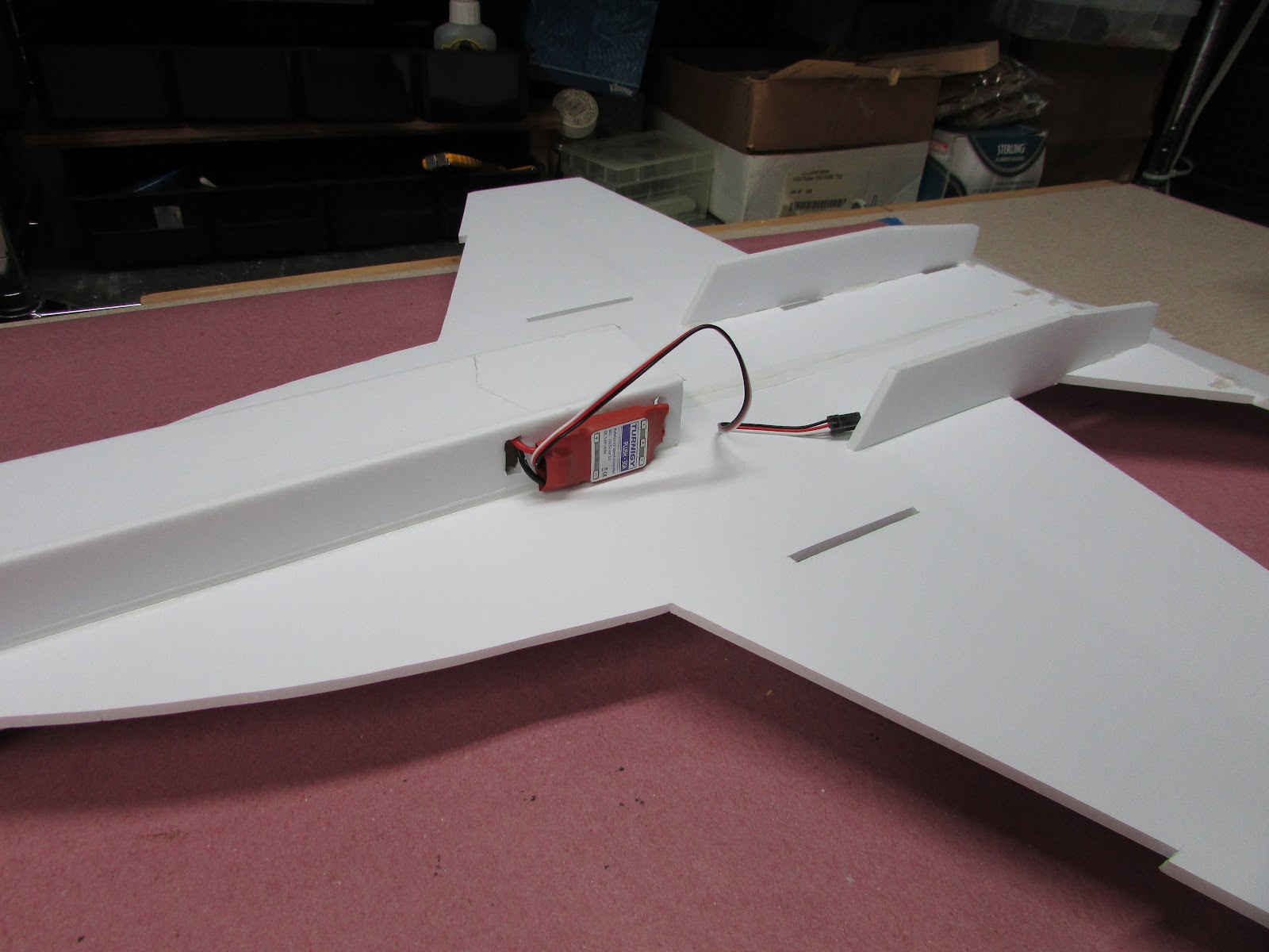
Place the ESC on the outside of the fuselage to increase cooling. It will be mostly concealed by the belly plate as long as it is near the rear of the fuselage.

Snake the ESC battery connection into the fuselage and then up into the battery hatch right in front of the motor mount.
Glue the servo nests in place.

Center the servos, attach the arms and glue the servos in place. The control rods (0.039” music wire Radical RC) on my builds are fed through the 3rd hole from the servo axis leaving four empty holes on the outside of the arm. Route and secure the wires and receiver. A while ago I learned that props cut wires really easily, so you don’t want them flapping around near the propeller. I use little strips of paper and hot glue to secure the wires. With the electronics in place, it is time to attach the belly plate.

The belly plate sides will extend from the point where the wing meets the leading edge wing extension and go straight back to the trailing edge of the wing. Run a bead of glue along the length of the belly plate sides (and tabs), along the top of the tail fuselage panels that are already attached to the wing and the fuselage where the front tip of the belly plate meets. Hold in place until the glue cools.

It looks like this when glued in place.
Cutting the propeller holes

Lay the propeller where it will go. Cut the hole to be about 2 cm wider than the propeller forming a bowtie shape.

The prop hole on the belly plate doesn't have to be as wide as the one in the wing, so I just cut it out to what I thought was a nice size.

The last step is to glue on the vertical stabilizers. Run a bead of glue down the underside of the stabilizer and plug it into the tab holes. After a few cooling seconds bend over and hold in place at the correct angle.
This build took 2 hours to print, tape and cut out and glue together. I put together a time lapse of the whole thing starting at 8:15 pm and ending at 10:20 pm. Adding the electronics took another 30 minutes.
Post-Build Comments
Flight results were great! I went out in the morning as a storm was approaching. Winds were expected to be gusts up to 60 MPH later in the day but the day started calm enough to fly.
The only complaint I have about the maiden of the v1 plane is that the field was a little dewey and this caused the belly plate to delaminate. I thought it flew really well for the powertrain used.
Flight results were truly awesome. Fast - wow, what a plane! It was so fun that had a hard time not giving it at full throttle all the time. Vertical climbs were easily performed. When flying at slower speeds, it seemed a bit tail heavy, but it may have just been the wind - it seemed to want to climb when flying upwind. Rolls, loops and turns were excellent. Roll control was less than snappy, but that can be adjusted in the rates of the radio. The wings started getting floppy during the flight - I could see them flex up and down in the wind, but I assume that was the foam core board getting damp from the moisture in the air (80% humidity that morning). I crashed the v2 twice during the maiden flight, not hard crashes. The first crash was my bad, I was turning from upwind to downwind and just not providing enough power and it stalled. It survived with only a few dirt marks on the nose. The second crash was due to losing power to the motor (ESC failure). Neither crash produced significant damage - it still flies!
The post crash analysis determined the 30A ESC from Grayson Hobbies failed.

I can’t tell if the ESC failed due to a faulty electronic component or moisture but nonetheless, it stopped working. It was being used within normal operating conditions - the motor/propeller combo on the plane draws 25-28 amps at full throttle, The positive outcome from this experience is that the plane glided very nicely without power. Following the maiden flight, I replaced the ESC and painted it.
I have to say that I really, really like the Ross Foam Core! It is just a little thicker and heavier than Readi-Board, but the paper covering doesn’t peel and moisture doesn’t seem to permanently debilitate it. Moisture will soften it up, but it eventually dries and regains its stiffness. Because it doesn’t peel with moisture, it can be painted. The above plane was painted with an airbrush using acrylic diluted 50:50 with water. The paint illuminated stress lines in the wings between the propeller hole and the tail. I’ll bet it will fail along that line at some point. To address this concern, in v3, I added a 3 mm carbon fiber tube to the wing panel. I’ve included those directions as optional, but highly recommended.

The larger higher kv motor used in v2 supports a smaller propeller - which is good news. As shown above, the propeller hole in v2 could have been 2 cm narrower (which I did cut to size in v3). To allow for either configuration, the plans have a dotted line for cutting out the prop hole. Just cut it out to match the propeller you choose.
*****************************************************************
UPDATE November 2015
Here is the maiden flight of the F-18v3. What a terrific flight! Needed no trip (or hardly any) to get stable flight. Another plane that is a joy to fly.
**************************************************************************
F-18 Versions/Statistics/Parts

F-18 v1 Statistics
Material: 2 sheets Readi-Board (Dollar Tree)
Weight: 263g
Battery: 1000 mAh 77g
Flight: Weight 340g
Wingspan: 66.2cm (26”)
Motor: D2822-1450kv (HK)
ESC: 18A Turnigy Plush (HK)
Propeller: APC 7x6 (Radical RC)
Static Thrust: 440g @15 Amp,
Thrust:Weight ratio:1.29
Servos: 2x 9g (HK)
Control Rod: 0.039” piano wire (Radical RC)
Receiver: OrangeRx 615x (HK)

F-18 v2 Statistics (bigger motor, ESC, Battery)
Material: 2 sheets Ross Foam Core (Walmart).
Weight: 308g (after paint)
Battery: 1300 mAh 40C114g
Flight Weight: 422g
Wingspan: 66.2cm (26”)
Motor: D2826-2200kv (HK)
ESC: 30A Turnigy Plush (HK)
Propeller: APC 6x4 (Radical RC)
Static Thrust: 740g @ 28 Amp,
Thrust:Weight ratio:1.75
Servos: 2x 9g (HK)
Control Rod: 0.039” piano wire (Radical RC)
Receiver: OrangeRx 615x (HK)
F-18 v3 Statistics (added CF Tube)
Material: 2 sheets Ross Foam Core (Walmart).
Carbon Fiber Tube wing spar, 3 mm (Radical RC).
Weight: 325g (after paint)
Battery: 1300 mAh 40C 114g
Flight Weight: 439g
Wingspan: 66.2cm (26”)
Motor: D2826-2200kv (HK)
ESC: 30A Turnigy Plush (HK)
Propeller: APC 6x4 (Radical RC)
Static Thrust: 740g @ 28 Amp,
Thrust:Weight ratio:1.68
Servos: 2x 9g (HK)
Control Rod: 0.039” piano wire (Radical RC)
Receiver: OrangeRx 615x (HK)
HilldaFlyer - October 2015
Join the discussion and follow other builders on the FT Forum
and you'll get exclusive content... Video of crashing and repairing the v3


Log In to reply
Log In to reply
Log In to reply
i want to build one of these!
Log In to reply
Log In to reply
That said, I do like what you did with this! Try tossing on a stupid large motor and some rudders and do 3D with it!
Log In to reply
Log In to reply
I highly recommend using ROSS foam core in the build and if you're up to it, a CF tube in the wing. The three versions I built have been flown again and again. The Readi-Board v1 has happy face wings now, warped from moisture and delamination. Both the ROSS foam core planes v2 and v3 are still really fund to fly. I like the v3 with the CF tube best - it really goes well.
Log In to reply
https://www.facebook.com/scott.day.754
Log In to reply
I flew mine again last weekend had the v1 with Readi-Board had smiley-face wings, so much dihedral that it would hardly turn. I'm in the process of updating with a video. Best to you.
Log In to reply
Log In to reply
http://forum.flitetest.com/showthread.php?22358-Community-Build-F-A-18-Super-Hornet-2B-the-FT-18-when-completed
Log In to reply
Log In to reply
Log In to reply
Log In to reply
Motor: D2822-1450kv (HK)
ESC: 18A Turnigy Plush (HK)
Propeller: APC 7x6 (Radical RC)
is really good. The fuselage width of this plane will not allow for a propeller larger than 7", otherwise I would suggest the motor/prop combination on the FT-22
Turnigy SK3 2822-1090kv with SF 8x4.5 prop. This alternative setup is pretty good for beginners, but you will soon graduate to the faster one. - See more at: http://flitetest.com/articles/glassed-ft-22#sthash.s4iz9YLU.dpuf
Log In to reply
Log In to reply
https://www.youtube.com/watch?v=-TPVfi51v5o
Log In to reply
Want to know how the F-18 survives a high speed crash?
Join the discussion on the FT forum:
Here is the URL - I don't know how to link it.
http://forum.flitetest.com/showthread.php?22358-Community-Build-F-A-18-Super-Hornet-2B-the-FT-18-when-completed&p=241469&viewfull=1#post241469
Log In to reply