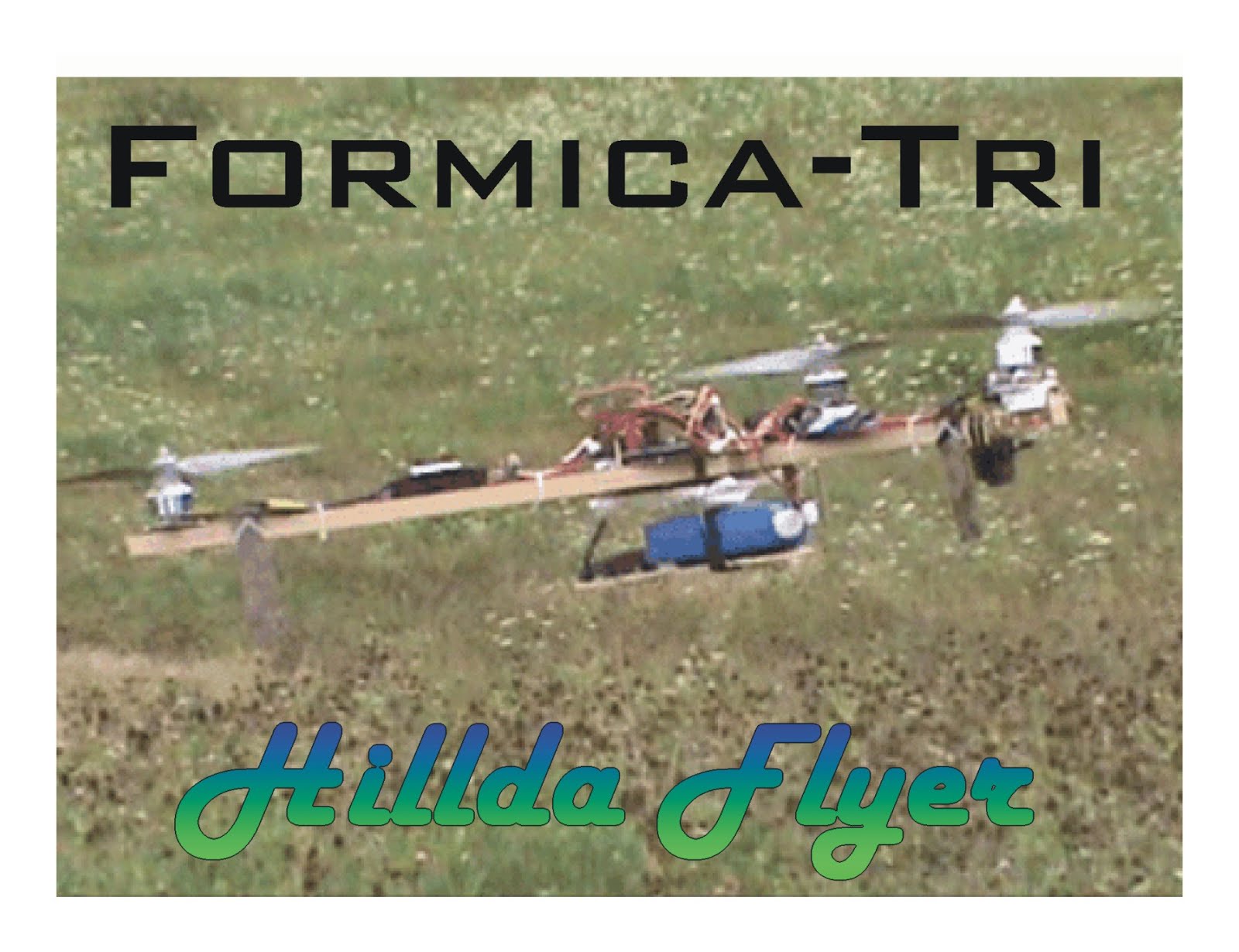
Formica-Tri
by HilldaFlyer

Hats off to David Windestål for all the effort and design of his tricopter. After building my Screeny EZ2 Build quad (http://flitetest.com/articles/quad), I was inspired by David’s tricopter design, especially making his first one with four independent gyros - wow, that was great work! Thanks to David and his frame plans, I set out to build my own tricopter with pieces of materials in my basement. I didn’t have any G10 fiberglass laminate laying around, but I did have some leftover formica countertop material. Formica is made of Melamine resin and paper, so it is not as strong as G10, but I thought it might be tough enough do the job, so I had to build it and find out. I have now built 2 versions of Formica-Tri, and will describe them below.
Version 1.0
The tricopter body is made of 1 ply formica. Formica is less expensive (free) and more readily available compared to G10 fiberglass sheet, however, it is not as strong. A bonus is that it comes in a myriad of colors and patterns.
The tail boom is cut longer to support the formica body.
The tail boom is attached to the body with two bolts, one bolt in the rear and one in the front taking the place of six bolts.
The vibration dampening battery and camera platform is simplified and attaches to the formica body with wire ties.
Version 1.1 (modifications to version 1)
The yaw mechanism was modified to include a control arm between the servo and motor swivel platform. It removed the yaw-shake that so many people have had trouble with - including my first build.
Implemented toothpick shear pins.
Version 2.0 (new build)
2 ply formica made by gluing two sheets of formica back to back. The results were great.
Used DT750 motors.
Slightly shorter booms
I have now flown the Formica-Tri v1 more than 50 times and I have crashed several times, three of which were significant enough for me to comment on the strength of the formica frame… it is very durable. The first crash was a front-on impact with the grass landing field going about 20 to 30 MPH. The formica-tri impacted the ground, flipped, bounced and cartwheeled a few times and survived the crash with only a broken prop. I believe the folding arms were both the cause of the crash and the reason there was not significant damage. The single layer of formica is not as stiff as G10, so I think one of the arms started folding back during flight which caused it to nose down into the ground. To prevent unintentional folding, I drilled a small hole in each arm boom and top formica frame to insert a toothpick shear pin (see v1.1 below).
The second crash was a reverse flying tail touch with pavement. The damage report indicated that the left boom was broken in two places, at the mount holes for the motor and at the holes where the boom is secured to the frame and two props were broken. The formica frame was not damaged in the slightest and the tooth pic shear pins broke as designed.
Version 1.1 Redesigned the yaw mechanism and added toothpick shear pins to the front booms.
Formica-Tri v1.1 received a redesigned the yaw mechanism that put the servo underneath the boom and connected it to the motor pivot with a control arm and linkage. This allowed for “gearing” of the servo movement and eliminated the yaw-shakes. It worked great.
The third significant crash was like the first. I was skimming across the grassy field and I hit some tall grass and tumbled. There was no catastrophic damage, but the shear pin took a chunk out of the formica frame.
Version 2. Stronger body and different motors.
To give the body more strength (heavy duty design), I glued two pieces of formica together, back to back, with epoxy prior to cutting out the shape. The 2 ply formica is very stiff and very strong, and just about the same thickness as the G10, but since it is not based with fiberglass fibers, it would utterly fail in a strength contest. However, since one layer of formica was tough enough to withstand all I have put it through, I’m sure the a double layer would survive anything an inflight catastrophe could dish out… My advice is - don’t crash, but if you plan on doing stunts or other crazy high speed flying through trees and next to brick walls or the ground, use the 2 ply formica, otherwise, the one ply formica should serve you well. However, after making the 2 ply formica, I liked the “feel” of it better. In version 2, I also tried out a different motor, the DT750, just like David’s first builds. You probably are asking yourself why I would switch from SK3 2826-1450 to DT750? I ordered them with the idea of duplicating David’s work, and while they are not as glamorous, the larger props gave a really smooth stable flight. V2 also has shorter booms
Symmetrical motor placement. In all of my tricopter builds, I have placed the motors completely symmetrical using the technique provided by CPO - Symmetrical Tricopter and T-Copter Design Theory. http://flitetest.com/articles/symmetrical-tricopter-and-t-copter-design-theory
The way I’ve done this is Iay out butcher paper on the workbench, lay the tricopter upside down and mark where the front motor shafts touch the paper. Draw an arc using one motor as the pivot point and the other as the radius. Repeat the arc drawing using the other front motor as the pivot point. Where the arcs intersect indicates where along the rear boom to place your tail motor. “X” marks the spot.
Formica-Tri V1
Materials:
Formica - leftover from construction.
Epoxy Resin 635 THIN EPOXY SYSTEM medium hardener from US Composites.http://www.shopmaninc.com/epoxy.html.
Saw to cut formica (scroll saw, jig saw with fine teeth 20/inch)
#6 bolts and #6 lock nuts or regular nuts with locktight
Drill and/or drill press, ⅛” drill and 5/64 drill
½” square dowel 1 yard (x2) - local hardware store.
4 mm Carbon Fiber rod or tube
Front Wheel Steering Arm & Mount Set 40mm (5sets) - Hobby King
Control board KK2.0 or KK2.1.5 - Hobby King
3 ESC (HK 20A flashed SimonK) - Hobby King
3 Motors (Turnigy SK3 2826-1240 short shaft Hobby King with APC 8x4.5 prop Ready Made RC).
Turnigy MG90S Metal Gear Servo - Hobby King
Cut ½” square dowel, 2 at 35 cm and 1 at 39.5 cm and four at 2 cm long. The tail boom is longer than David’s because it extends the length of the frame. At times, I found it really hard to find straight ½” square dowels in my local hardware supply. As an alternative, I have also made some booms by gluing two ¼” x ½” molding together, which seems to be straighter and stronger (and about twice as expensive).
Mark the tail boom at 10.6 cm. Just lay the boom onto the template and mark where the side riggers should go.

Glue the four 2 mm pieces to rear boom at the top and at the marks with wood glue. Clamp and let the glue dry while you are doing the next steps.

Print and cut out the plans (attached pdf). Before cutting out the body, Use hot glue to attach the 2 pieces of formica for the body together. Attaching the pieces together ensures the edges and holes are aligned. I would recommend the heavy duty design (v2). Make the formica 2 ply by gluing two pieces of formica back to back with epoxy. Use Elmer’s glue to attach the plans to the formica sheets.

Cut out the frame and drill the holes. Sand the edges flat using a large surface. To get the holes in the right place, I use a punch to dent the center of where the hole should go. Note that there are a few holes that will only get used in the top plate, but there is no harm in drilling both top and bottom plates. All holes are ⅛” except for the 5/64” holes for the battery/camera tray wire hanger (0.047” piano wire).

After you are done drilling, cutting and sanding, separate the formica bodies by heating it with hairdryer. After a minute or two/five, the hot glue will warm enough to separate formica sheets. Scrape off the excess hot glue with a paint scraper or razor blade. Remove the paper template by moistening the formica body with water to remove paper plans from surface.
To drill the holes in the booms, position the tail boom under the top body piece and mark the location for the hole at the front. Remove the tail boom and make sure the mark for the hole is positioned in the middle of the boom. Drill the hole centered in the tail boom. Bolt the formica body to the tail boom with the hole you just drilled. With the tail boom secured at one end, mark the placement of the hole at the rear of the body. Remove the boom from the body and drill the hole in the center of the boom at the proper location. In the photo below, these two holes are the ones in the tail boom. The front “T” has the holes drilled for the wire ties but the back does not. I’ve drawn on the “T” and back mount the path to drill holes where the wire tie will pass.

Bolt the top and bottom plate to the tail boom with two 6-32 ¾” bolts. Drill the holes for the wire ties that hold the battery/camera tray.To protect the battery from the bolts, you may wish to overlay the bottom plate with foam core board. With 2 ply formica, the bolts are just the right size and there wasn’t much bolt sticking out of the bottom of the nut - another PLUS for 2 ply formica!

Mark the placement of the motor mounts on the two front booms and drill holes. The size of the hole depends upon the type of mounting hardware you will be using and the type of motor. Since I am using Turnigy SK3 2826-1240 motors, I drilled a large hole for the motor shaft and two ⅛” holes for the motor mount. I use a #6-32 bolt to mount the motor to the boom. Next time I am going to purchase short shaft motors so I won’t have to compromise the strength of the boom with a hole for the motor shaft.

On the body side of the boom, I drill a ⅛” hole 1.8 cm from the end in the center. This will be the location of the bolt that holds the boom to the body.
Yaw Mechanism version 1 (per David’s instruction with minor alterations.)
http://flitetest.com/articles/tricopter-scratch-build
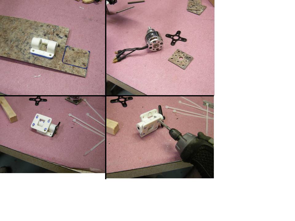
To attach the SK3 Motor to the yaw mechanism, I built a square motor mount out of formica that matched the holes to the back of the motor and aligned with the holes on the yaw mechanism. The yaw mechanism was a brilliant design made from a front gear steering hinge. The motor mounting bolts stuck out of the formica a little so I sanded away some of the plastic “+” to allow clearance.


Battery hanger and camera tray
The battery hanger and camera tray is pretty much the same type of vibration dampening system used by David, but the following design has fewer bends so it is a little bit easier to make and attach than the wire sandwiched between wood.
Cut two pieces 25 cm long pieces of .047”piano wire. Mark the wire at 1, 3.5, 10, 15, 21.5 and 24 cm the end. At points 1 cm from each end, bend a 90 degree turn. The next 2.5 cm leave straight and then bend a nice half circle between 3.5 and 10 cm from each end. this will leave a 5 cm straight for mounting the battery/camera tray.

I used a piece of 3 ply plywood from a tangerine box or, as pictured, a piece of flooring underlayment for the battery hanger tray. Feed 3” wire tie through the holes drilled at a diagonal from the wire direction then insert the ends into the center hole in the bottom. Wrap the wire tie around the wire and feed it back through the 45 degree angle hole. Snug down the wire tie.

The battery platform and camera tray is secured to the wire harness with wire ties through the two converging holes drilled into the body and T frame. Push the end of the wires into the small holes in the bottom plate of the Formica-Tri. The fit is pretty snug, just wiggle the wires around a bit and they’ll push in.

Run the wire tie through one hole, around the wire hanger, up through the angled hole and then through the fastener. The forward/backward movement is inhibited by the vertical ends of the wire harness.


Formica-Tri v1.1
Addition of the shear pin - Because the single layer (1 ply) of formica is kind of flimsy, I decided to put shear pins into the arms so they wouldn’t fold mid-flight or hitting grass. I drilled a small hole through the top formica body and all the way through the wood boom without drilling through the bottom body plate. If I ever build a 1 ply formica-tri again, I would put the shear pin hole further from the edge of the body. In a hard crash, the pin broke and tore a chunk out of the body.

Yaw Mechanism for Formica-Tri v1.1
I noticed while flying my Formica-Tri v1.0 that the yaw mechanism had to move very little in order to have pronounced yaw effect on the tricopter. It seemed that every movement in the yaw mechanism was conducted to the control board and an oscillating motion ensued which I termed the Yaw-Shakes. I was unable to eliminated the yaw-shakes, even with setting the servo dampening on the KK2.1.5 board to 90% - 95%. I thought about this and researched other people’s online posts regarding the shaking yaw mechanism and it seemed like most people tried to solve this by using a digital servo, which has a smaller dead band than an analog servo. The other potential source of the yaw-shakes was the slop in the homemade yaw hinge itself. I don’t have a 4 mm drill bit so the hole was a little larger than the carbon fiber shaft allowing the yaw hinge to rock a bit on the hinge shaft.
To get a tighter fit for the yaw hinge, instead of drilling the holes in one of the white plastic steering hinges larger to accommodate the 4 mm carbon fiber tube, I reduced the diameter of the 4 mm carbon fiber tube by putting it into a drill and sanding it with 120 grit it until it would barely fit through the steering mechanism and freely twist but without any slop. This worked fantastic. The carbon dust even acted like graphite to lube the hinge.
Another thing I wanted to try was to introduce a linkage between the servo and the yaw mechanism so that large servo movements could be geared down to produce small yaw movements with large servo movements. However, with the direct-drive servo connection to the yaw mechanism, it is impossible to alter the ratio of servo movement to yaw movement. To build the geared system I attached a servo arm to the yaw mechanism and fixed the servo to the bottom of the boom with piano wire linkage.
These two changes completely alleviated the shaking of the yaw mechanism that I, and so many others, have encountered. Notably, I still use a $5 metal gear servo and not a pricy digital servo.
Here is how it is done:
Reduce the diameter of the carbon fiber tube by sanding with 120 grit sandpaper. Fasten the carbon fiber tube in the drill and while spinning at the fastest speed, slide the sandpaper along the length of the saft. Test the size of the tube each two to three passes

Sand steering mechanism risers for non-binding fit so that both freely rotate after the rod is slide into place.

Sand of both sides of a servo arm and attach it to steering plate with super glue. Use a wire or toothpick to align the servo arm with the center of the hinge. Drill holes through the servo arm and nylon steering hinge (1.5 mm if you are going to use servo screws to attach). Fix the servo arm to the steering hinge with servo screws and put a dab of hot glue on the other side so the carbon rod doesn’t slip out.

Make motor mount to join the steering hinge to the motor. Draw the shape of the hinge onto a piece of 2 ply formica (or G10 if you have some, 1 ply formica is not strong enough). Draw on the formica where the holes for the steering plate and motor mount. Drill the holes. Use a large drill to add a counter sink for motor mount screws. To get the steering hinge to hold to the wood boom, the holes need to be elongated. A rotary tool does the job very nicely.
Attach the yaw mechanism to the boom with wire ties. Attach motor mount plate to yaw mechanism with wire ties. Attach the servo to the underside of the boom with wire ties. To get the servo to be really stable, a piece of popsicle stick was hot glued to the boom to keep the servo from twisting because it is slightly smaller than the boom.
The legs used are 2 ply formica 8 cm long with a single hole 0.5 cm from one end. Secure it to the boom with two wire ties.

Assemble the Formica-Tri with your favorite electronics.
Formica-Tri v1.1

Formica-Tri v2
Formica-Tri v2 is almost identical to v1 except it is made of 2 ply formica, the booms are slightly shorter and the powertrain uses DT750 motors. Formica-Tri v2 had a different power train, so I modified the booms by making them shorter and implementing a step motor mount so the motors don’t stick up out of the body plane as much.
Arm booms were 29.5 cm with a 3 cm extension for the motor (5 cm including the overlap).

The tail boom was 40.5 cm long with a 5 cm extension for the yaw mechanism. To make the tail motor set at about the same height as the front motors, the extension was modified to be two boom heights thick, all held together with wood glue. Two holes were drilled through the extension for fastening the servo with wire ties.


Here are the two powertrain setups that I have tried. The DT750 motors are very smooth and quiet and gave a great ride. A bearing went bad in one of the motors so I have only flown it a half dozen times. My recommendation is the SK3 if you are planning on performing acrobatic maneuvers but the V2 setup is great for floating around.
Formica-Tri V1 Powertrain
KK 2.1.5 flight control board - Hobby King
HK 20A ESC flashed SimonK - Hobby King
SK3 2826-1240KV motors - Hobby King
APC multicopter 8x4.5 props Ready Made RC
Formica-Tri V2 Powertrain
KK 2.1.5 flight control board - Hobby King
HK 20A ESC flashed SimonK - Hobby King
DT750 motors - Hobby King
Gemfan ABS Propeller 10x4.5 props - Ready Made RC


Log In to reply
Reply | Remove Comment
- See more at: http://flitetest.com/articles/formica-tri#sthash.S8fgVu3Y.dpuf
Log In to reply
Log In to reply
Log In to reply