Calculating the Center of Thrust on Multirotors
Why would you want to calculate the center of thrust of a multirotor?
Knowing the center of thrust (CT) helps a lot to build a multirotor that uses all of its motors as effective as possible. Because if you make sure the center of mass (CM) is at this point, all of your motors can run at the same speed to achieve a stable hover.
If your CM is moved forwards, the front motors have to work harder to keep the multirotor level.
Let's go back to school
So, the task is to find the center of thrust for a set of motors. This is similar to finding the center of mass for a set of objects with the only difference being that our motors produce lift or „negative mass“. You might have heard about calculating this in your physics class. The keyword to look for in your old books is "weighted average".
Let's start with a very simple setup and have two motors, each producing the same amount of thrust t1 and t2 of 100g each.
The distance between the centers of both motors is 10 cm.

To calculate the center of thrust between those two, we have to set a start point for measuring the required distances. To make this easy, we just use the center of motor 1 for the calculation. This results in two distances. The distance l1 to motor 1 being 0 cm and l2 to motor 2 being 10 cm.
The formula to find the center of thrust CT now becomes:
![]()
So the distance to the center of thrust from motor 1 is 5 cm – exactly in the middle as you might have expected.
This works no matter where we put the start point. If we had chosen the center between both motors, the distances would be l1 = -5 cm (to the left) and l2 = 5cm:
![]()
So with 0 cm it would be exactly at the chosen midpoint again.
Making things easier
All these numbers make things look complicated. So instead of 100g of thrust let's just use 1 g in the following calculations. After all that should not change the CT, right?
![]()
Right.
Changing thrust
Let's play with the thrust and make motor 2 more powerful, perhaps by changing to a bigger prop. So let's make t2 three times more powerful: 3 g, which changes the last formula to:
![]()
This made the center of thrust move 2.5 cm to the right of the center. Just as we should've expected.
Extending to more motors
To extend this formula to more motors, we just do the following:

The part on the right just shows how lazy mathematicians are. It is a shorthand form of the left, with the sum symbol saying that for every motor you need to add one more "thrust times distance" multiplication on the top and one "thrust" value on the bottom of the fraction line.
So now we can add a third motor to our setup:
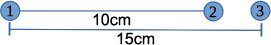
Without a lot of explaining text, let's just enter these values in the formula. Oh and all three motors have the same amount of thrust again.

So the center of thrust is 8.33 cm right of the center of motor 1 - a little more to the right than with the two motor setup.
Going multi-dimensional
How can we transfer this to a quadcopter where the motors are not in one line? For example like on the Electrohub in the spider configuration like this?

This is actually easier than I had first expected. Basically instead of one line, you use two by switching to an XY coordinate system.
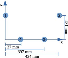
Now let's put these values in our formula for the X axis:

So the center of the thrust on the X axis is located exactly in the middle (434 mm / 2). Which you hopefully expected because quads usually are mirrored at the roll axis.
But what about the other axis?

The center of thrust on the pitch axis would be 140 mm in front of motors 3 and 4. I've marked that point in the sketch above and it is exactly the location people suggested for the flight controller on this Electrohub configuration.
The combined center of thrust is the point of intersection between CTx and Cty.
Time to play
What can we do with this knowledge now? Well first you can try to match the center of trust and the center of mass of the copter - of any copter to be precise. Putting the flight controller at this point will help building an efficient and stable multirotor.
Some might say, this is not necessary at all, because most flight controllers will compensate for any differences and still be able to fly nicely. That is true, but I somehow like to know what would be the „perfect“ setup.
If you don't like the position you calculated, you can always try and modify the variables. The length of the arms can quite easily be modified for example.
Another option is to try and modify the thrust you get from a set of motors. So if you want to move the flight controller more to the center of the Electrohub frame, you need to have less thrust from the two back motors than in the front. To do that, you can mix different KV motors and/or propeller sizes front to back.
Or you can tilt the back motors so they produce less thrust downwards. This is the V/A-tail setup some people use.
Calculating V/A-tail thrust
Ok since I mentioned it, I also thought (a while) about how to calculate the thrust when you tilt a motor. But what formula can we use for that? The following diagram shows what is happening.
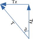
Instead of lifting straight up, the total thrust (T) now pulls up (Ty) and to the left (Tx). When both motors in the back are tilted at the same angle, but in opposite directions, the Tx of both evens out. So we can ignore that.
But the Ty still is working upwards, just not with the full amount of force T anymore. You can see that the Ty arrow is shorter than T in the diagram.
A triangle, an angle, a hypotenuse T, … Wait. This looks like trigonometric functions. Remember when you said you'll never need this kind of math after school? :)
Dig deep and you might remember the mnemonic „Soak-a-toe“ - or „SOHCAHTOA“? The letters CAH in this stand for „cos“, „adjacent“ and „hypotenuse“ in this formula:
![]()
We want to find Ty, so we have to transpose it and enter our simplified value of 1 g of thrust and an angle of 40°.

So the back motors will only produce 0.766 g of lift straight up each. Since everything is still symmetrical around the roll axis, we can ignore CTx, but what about CTy?

Compared to the 140 mm we had before, the CTy now moved 19 mm more to the front. We'd need 20 mm more to have it in the Electrohub center, but I wouldn't tilt the rotors any more than 40° ;-).
Conclusion
The math might look difficult in the beginning, but you can make it easier by simplifying the values for the thrust. As long as the motors and props are the same, these placeholder values works just the same as a possible real world thrust.
This makes it easy enough for all kind of multirotors, no matter how weird the arms are positioned or how long they are.
Usually it is not necessary to do these kind of calculations, but it doesn't hurt to know how to use them either. And you finally have a reason to actually use something you learned in school.
Thanks to CraftyDan who pointed me in the right direction while thinking about how to calculate this by mentioning the magic keywords and proofreading this article. :)


Log In to reply
I'm german too, but I like it simple. (and I was really good in mathematics)
Log In to reply
Log In to reply
You Could implement in your model the interference of propellers depending on distance, position and angle. That would be interesting.
Log In to reply
For a Quad copter - CoT is always halfway between the front and rear motors.
In your example above the CoT is 140.5mm which is half of 281mm. No need for complex formulas at all. Just divide spacing front to rear by 2.
For a Hexacopter - Measure the distance from front to mid motors - e.g 140mm. Then measure the distance from front to rear motors e.g. 310mm.
Add the two distances and divide by 3.
i.e. (140 + 310) / 3 = 150mm CoT is 150mm from front motors.
Here is an excel sheet that does all the work for you, it works for Quads, Hex's and V-Tails.
https://www.dropbox.com/s/h1kc8p9v034a1uw/NAZE%20MIX%20EDITOR%20V4.xlsx?dl=0 -
Log In to reply