
FrSky R-XSR FPort Modification
HilldaFlyer, November 2019
Abstract
Modify the FrSky R-XSR receiver so the native non-inverted FPort signal is delivered to the Rx’s connection plug.
The first receiver I modified so the non-inverted SPort or FPort signal was provided to the receiver’s plug was the FrSky XSR (FRSKY XSR FPORT MODIFICATION). The XSR is a bit big for some of the smaller quads I’ve been building lately. I wanted to use the R-XSR which is about 50% smaller. Unlike the XSR, the R-XSR has solder pads exporting the non-inverted SPort and SBUS signals. The goal of this modification, like the last one, was to get the non-inverted FPort signal to the receiver’s plug so there wouldn’t be extra wires hanging off a pad.

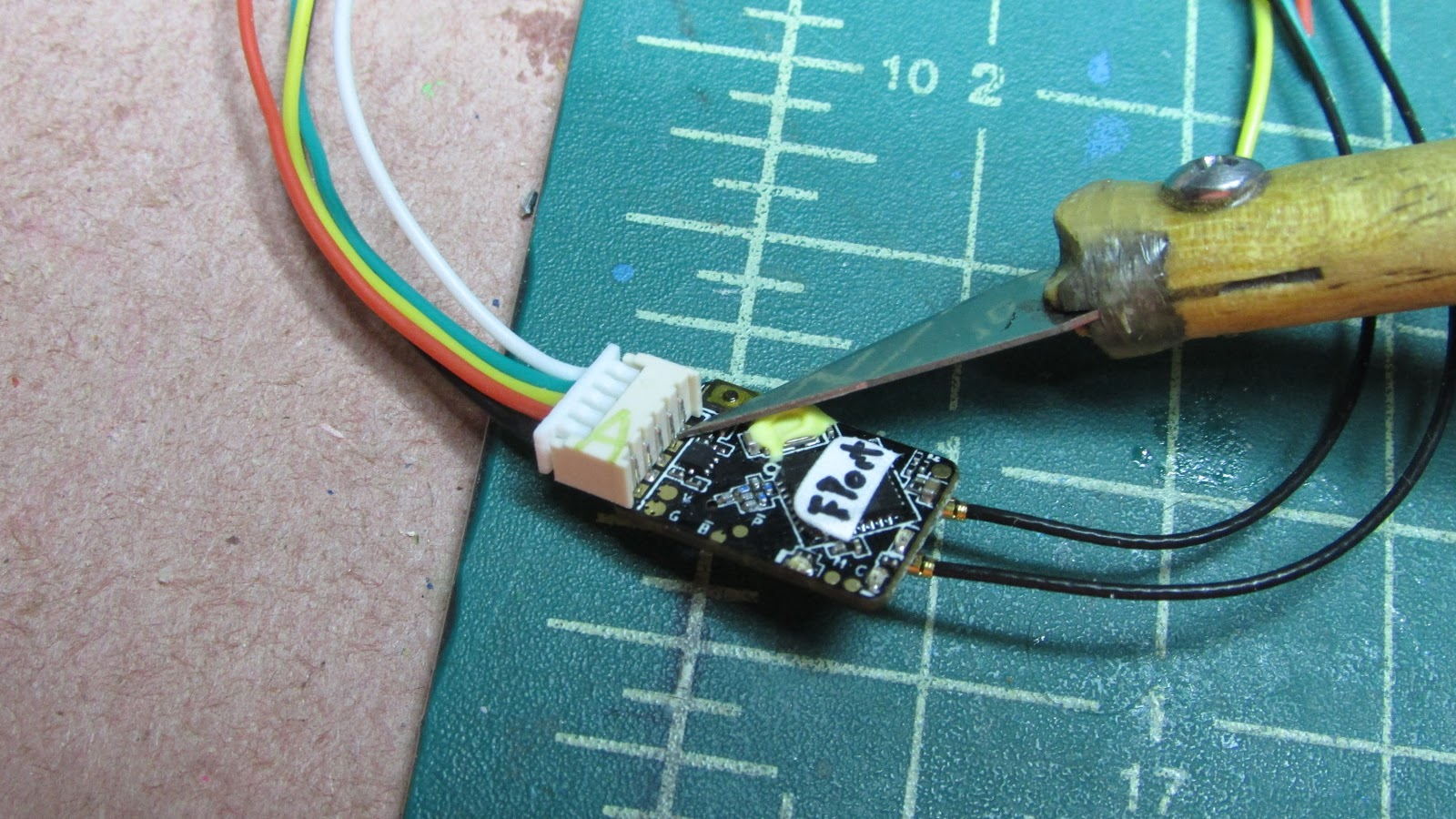
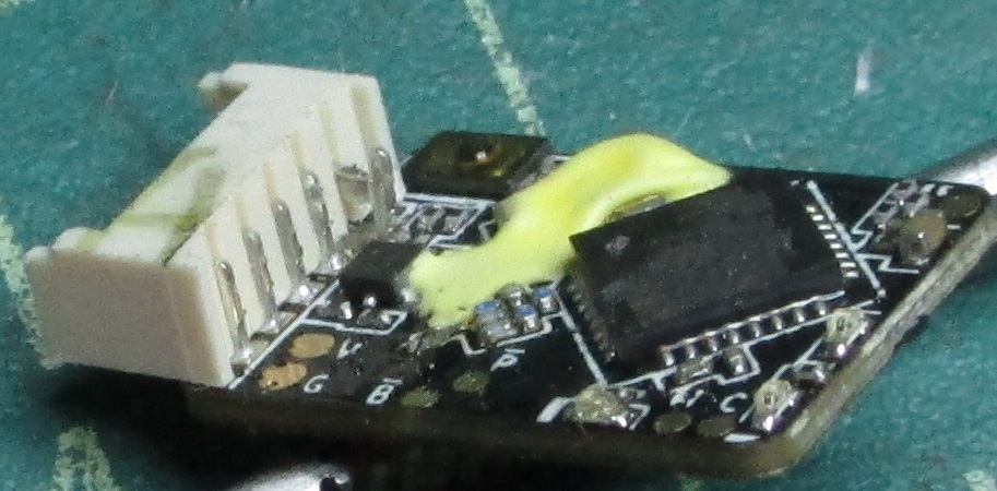
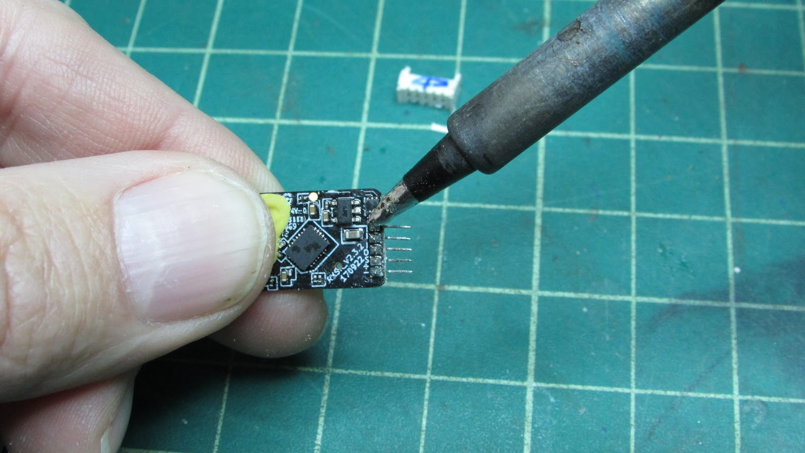
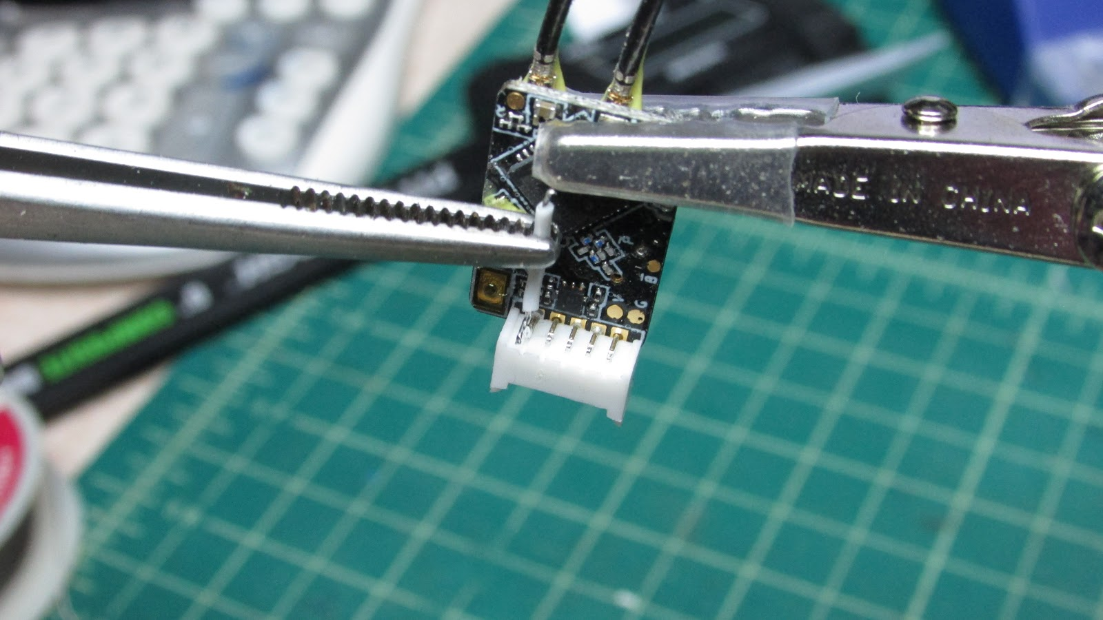
On the native receiver, the arrow points to the pads marked with overscore “B” and “P” which produce the non-inverted SBUS and SPort signals. After flashing the R-XSR receiver with the FPort firmware, the SPort pad and pin are converted to the FPort protocol.
On the plug, the fifth pin up from GND is the SBUS-In, which is only used if you want to put multiple receivers in series. However, this function is completely useless for a one receiver build. This seems like a nice candidate for the output of the non-inverted FPort.
The first task is to disconnect the pin from the board to make it a stand alone pin. I started tracing the continuity of this pin to components on the board, but there were several so I didn’t attempt removing all the connected components to isolate the pin. I thought the most direct method would be to separate the pin from the board.
The First Way
The first time I tried disconnecting the SBUS-In pin from the board, I used an exacto knife to cut through the pin.
This took some careful work and just seemed hard, besides, it ruined my exacto blade’s edge. I put the point of my exacto blade on the base of the pin solder joint and wiggled it back and forth until the blade cut through the pin.
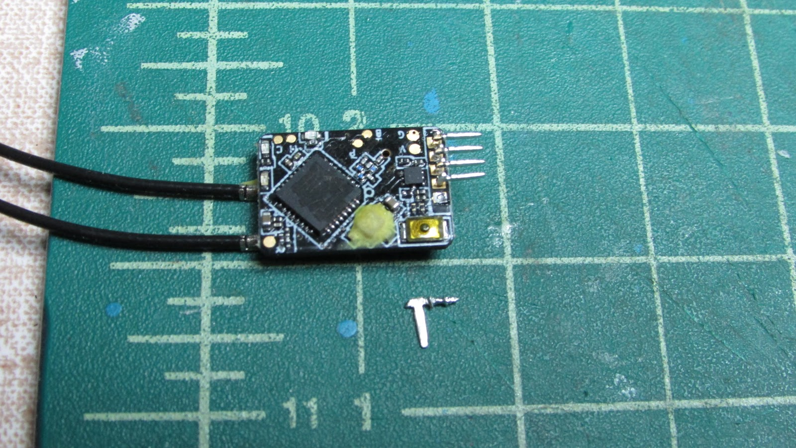
After it is cut from the board, push the pin from the plug side and it will slip out the back.

The pin is “T” shaped. The left part of the “T” cross above was the one that was cut from the board, it looks a bit damaged. It needs to be shortened so that when replaced into the plug it doesn’t contact the board.

Just clip or sand off that leg so that it is shorter, but don’t remove it completely, it is needed to keep the pin from sliding out the front of the plug. Slide the pin back into the plug with the shortened “T” side down.

Solder a small wire from the pad labeled overscore “P” to the remnant of the SBUS-In pin. This will conduct the non-inverted FPort signal to the 5th pin from GND.
The Easier Way
On my second modification, I came up with a procedure that was much easier, at least for me.
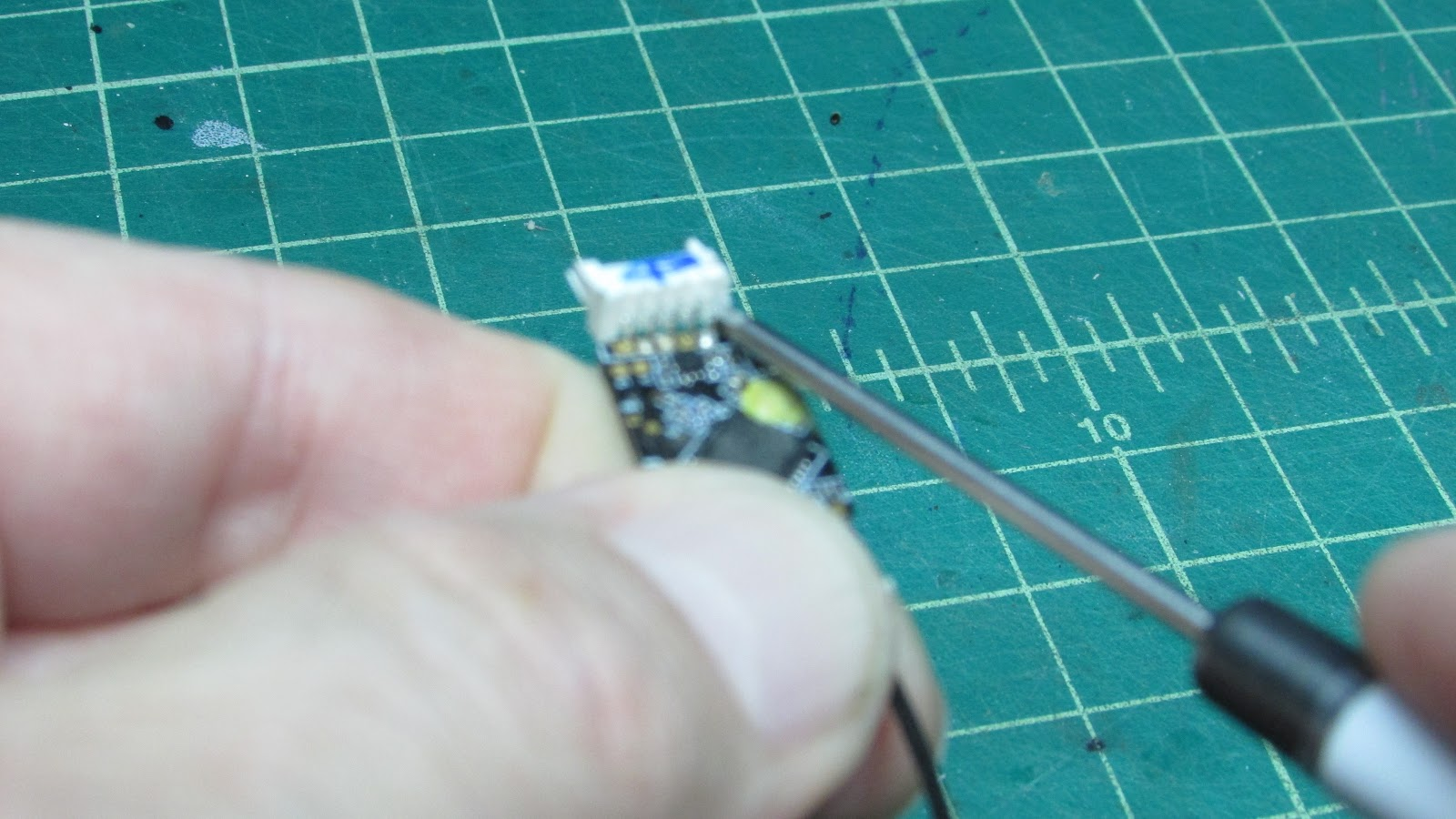
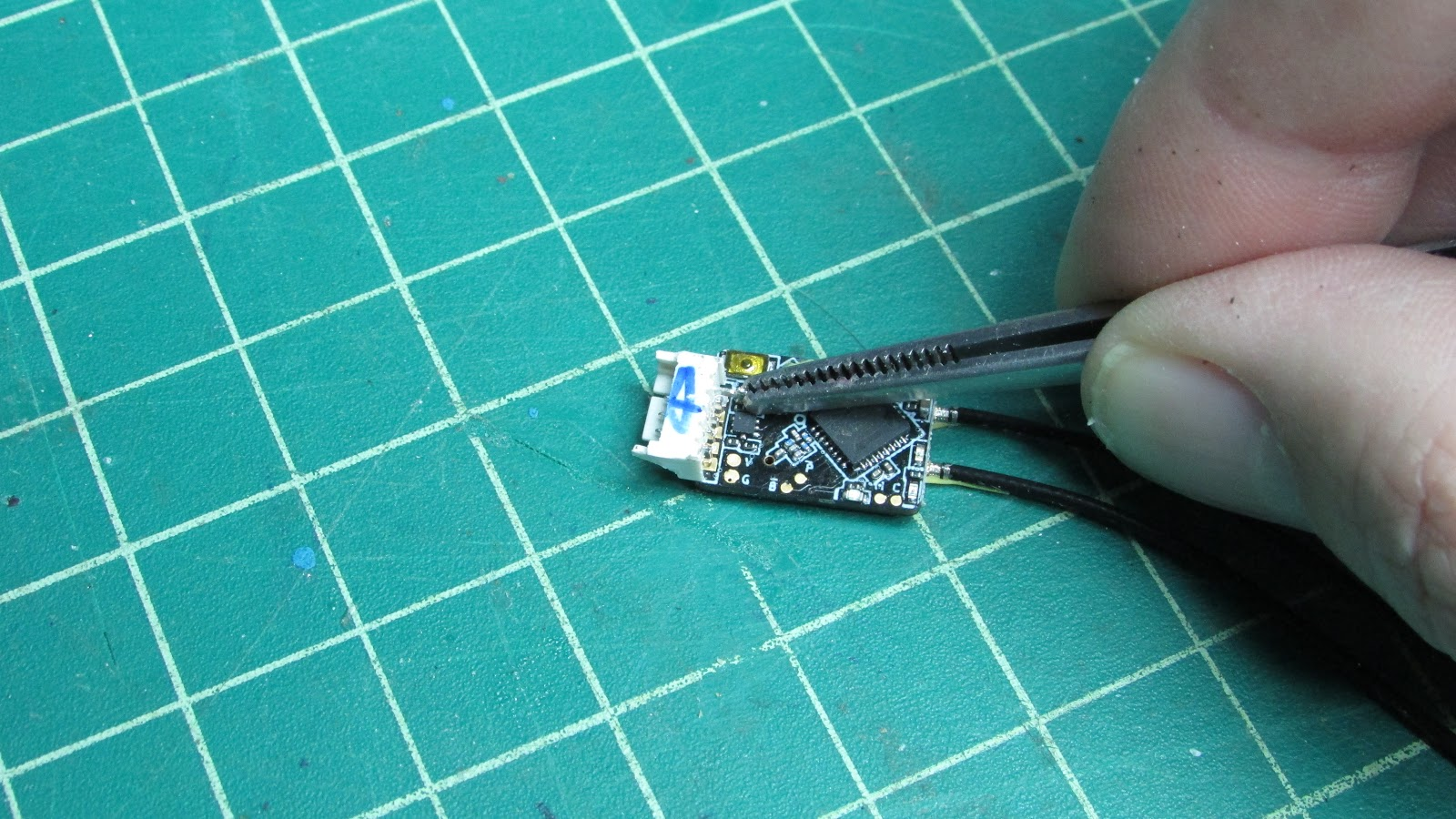
Use a screwdriver or some other tool to push the plug housing off the 5 pins. Push on the either end of the plug rocking it back and forth until it slides off.
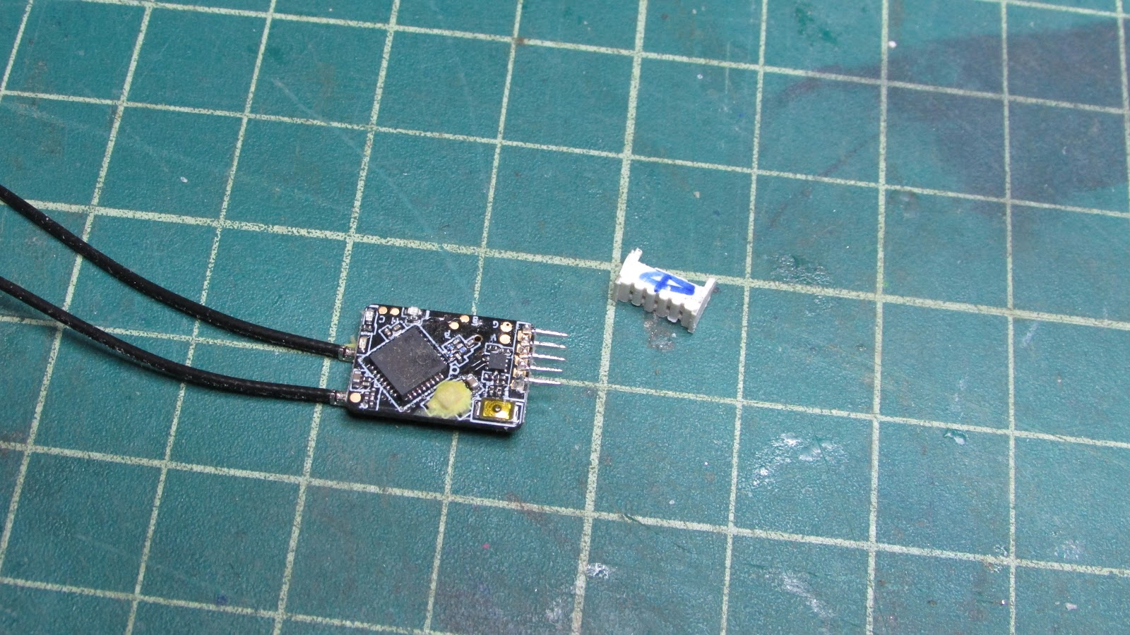
Desolder the 5th pin and remove it from the board.
The pin that was soldered to the board will need to be shortened so that it doesn't contact the board when reinserted. It can be shortened with clippers, sandpaper or rotary cutter - try not to bend the rest of the pin.
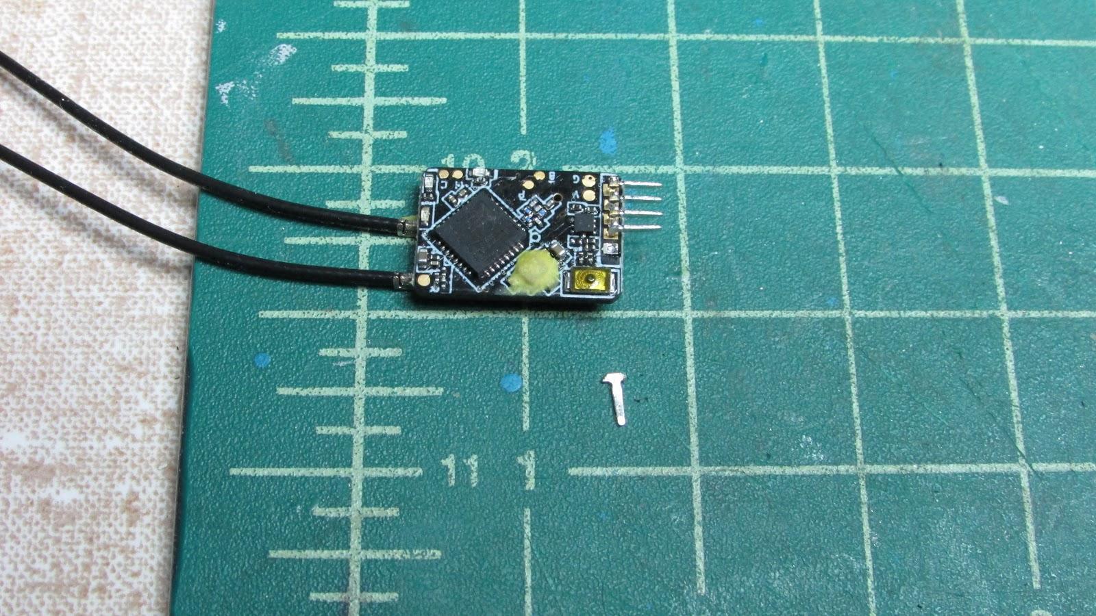
Here is the pin after I used a rotary grinder to remove the previously soldered long side.
Replace the plug housing by sliding it over the four remaining pins. Slide the fifth pin through the back.
Solder a small wire to the pin that is not connected to the board.
Solder the other end of the wire to the “P” pin .
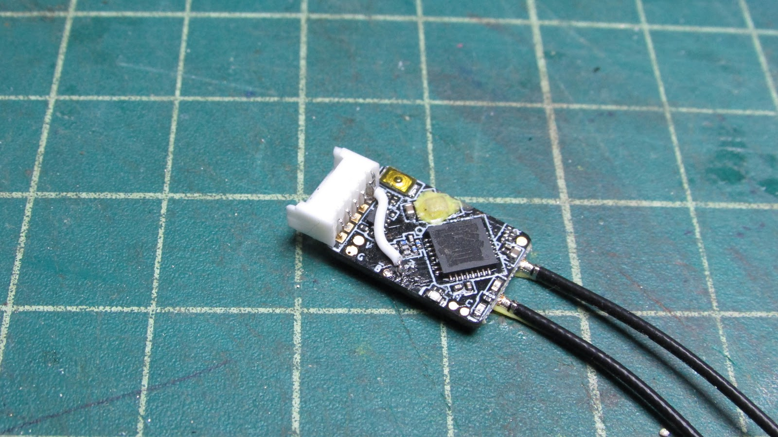
Here is the end product. Clean!

HilldaFlyer
November 2019
References
What is FPort?
Many of you will already know that FPort is a bi-directional communication protocol or interface between the receiver and flight controller (Reference: BetaFlight information:The FrSky FPort Protocol). FPort protocol was a collaboration between BetaFlight developers and FrSky which was a announced in December 2017. In simple terms, Fport is a combination of SBUS, Sport and RSSI into one wire. This function really comes in handy when connecting your receiver to a flight controller that has a limited number of UART pads.
--------------------------------------------
Joshua Bardwell - Notes
While doing my research for this project I got really excited about FPort because Joshua Bardwell stated @4:47 Josua "FPort is gets rid of the inversion issue. With FPort the protocol can be either inverted or un-inverted, so if you have an F4 flight controller you can put it on any UART pad that you have available."
@6:06 Joshua again reiterates, “So, FPort is just SmartPort plus SBUS on a single wire and no more inversion hassle”.
However, those statements turn out to be a presumption… in the comments:
“Are we sure about no more inverter hassle? The last time I checked, I still can't get FPort to work on most F4 FC, without applying the "uninverted hack" by soldering a wire to some tiny pad or chip leg. That's if the RX has an uninverted pad to solder. The new RX like R9 Mini doesn't seem to have an uninverted pad to hack, and fport didn't really solve the inverter issue.”
Joshua replied: “Yeah I think you're right. I was under the impression they were going to release an inverted-hack FPort firmware. But it seems that hasn't happened.”
----------------------------------------
Excellent resources
Oscar Liang - How to setup FrSky Fport
Joshua Bardwell - FRSKY FPORT HOW TO | SBUS and SmartPort on One Wire


Log In to reply
Log In to reply
Then I soldered the wire between the disconnected connector pin and the P pad just like you do.
I'm happy to provide images showing which track to cut and which component to remove, if you'd like.
Cheers,
Oliver
Log In to reply