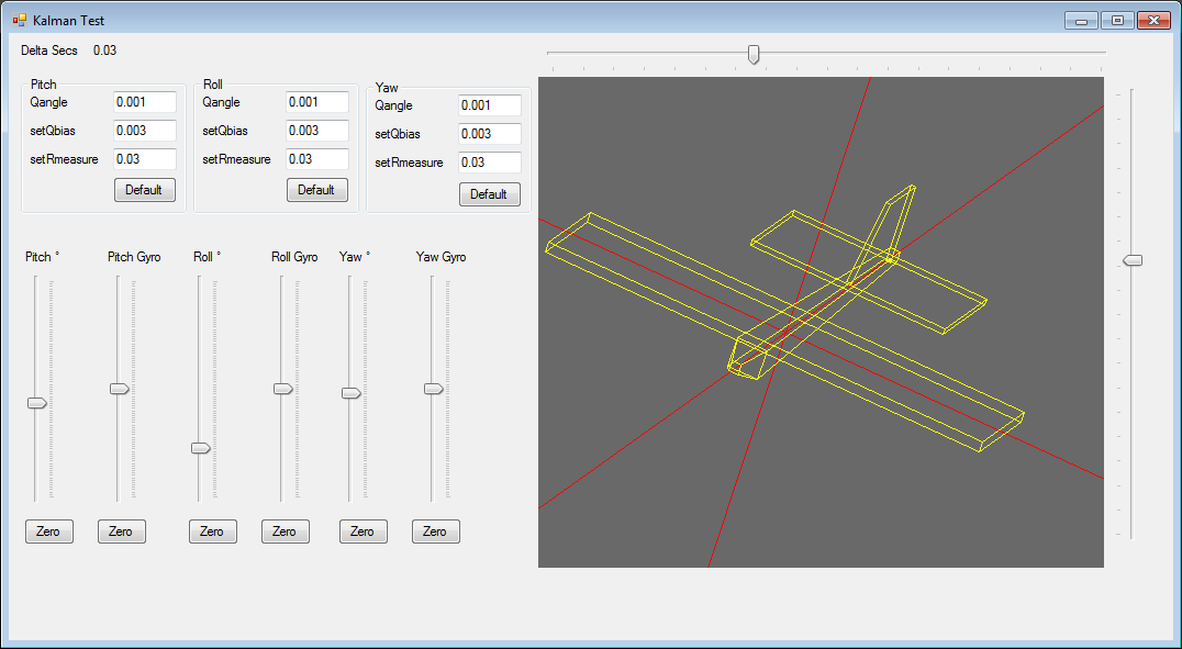
Kalman filter test harness with mimic C# code converted from Arduino code originally writen by Kristian Lauszus, TKJ Electronics.
Here is the Arduino code for same Arduino Code
The filter inputs in the test harness are driven from the sliders but could easily be fed from a real sensor. Another day perhaps?
The whole project is here Kalman Test
The C# class
/* Copyright (C) 2012 Kristian Lauszus, TKJ Electronics. All rights reserved.
This software may be distributed and modified under the terms of the GNU
General Public License version 2 (GPL2) as published by the Free Software
Foundation and appearing in the file GPL2.TXT included in the packaging of
this file. Please note that GPL2 Section 2[b] requires that all works based
on this software must also be made publicly available under the terms of
the GPL2 ("Copyleft").
Contact information
-------------------
Kristian Lauszus, TKJ Electronics
Web : http://www.tkjelectronics.com
e-mail : kristianl@tkjelectronics.com
*/
using System;
using System.Collections.Generic;
using System.Linq;
using System.Text;
namespace KalmanTest
{
public class Kalman
{
/* variables */
double Q_angle; // Process noise variance for the accelerometer
double Q_bias; // Process noise variance for the gyro bias
double R_measure; // Measurement noise variance - this is actually the variance of the measurement noise
double angle; // The angle calculated by the Kalman filter - part of the 2x1 state matrix
double bias; // The gyro bias calculated by the Kalman filter - part of the 2x1 state matrix
double rate; // Unbiased rate calculated from the rate and the calculated bias - you have to call getAngle to update the rate
double[,] P = new double[2,2]; // Error covariance matrix - This is a 2x2 matrix
double[] K = new double[2]; // Kalman gain - This is a 2x1 matrix
double y; // Angle difference - 1x1 matrix
double S; // Estimate error - 1x1 matrix
public Kalman() {
/* We will set the varibles like so, these can also be tuned by the user */
Reset();
// Reset bias
// Since we assume tha the bias is 0 and we know the starting angle (use setAngle),
//the error covariance matrix is set like so - see: http://en.wikipedia.org/wiki/Kalman_filter#Example_application.2C_technical
SetDefaults();
}
// The angle should be in degrees and the rate should be in degrees per second and the delta time in seconds
public double getAngle(double newAngle, double newRate, double dt) {
// KasBot V2 - Kalman filter module - http://www.x-firm.com/?page_id=145
// Modified by Kristian Lauszus
// See my blog post for more information: http://blog.tkjelectronics.dk/2012/09/a-practical-approach-to-kalman-filter-and-how-to-implement-it
// Discrete Kalman filter time update equations - Time Update ("Predict")
// Update xhat - Project the state ahead
/* Step 1 */
rate = newRate - bias;
angle += dt * rate;
// Update estimation error covariance - Project the error covariance ahead
/* Step 2 */
P[0,0] += dt * (dt*P[1,1] - P[0,1] - P[1,0] + Q_angle);
P[0,1] -= dt * P[1,1];
P[1,0] -= dt * P[1,1];
P[1,1] += Q_bias * dt;
// Discrete Kalman filter measurement update equations - Measurement Update ("Correct")
// Calculate Kalman gain - Compute the Kalman gain
/* Step 4 */
S = P[0,0] + R_measure;
/* Step 5 */
K[0] = P[0,0] / S;
K[1] = P[1,0] / S;
// Calculate angle and bias - Update estimate with measurement zk (newAngle)
/* Step 3 */
y = newAngle - angle;
/* Step 6 */
angle += K[0] * y;
bias += K[1] * y;
// Calculate estimation error covariance - Update the error covariance
/* Step 7 */
P[0,0] -= K[0] * P[0,0];
P[0,1] -= K[0] * P[0,1];
P[1,0] -= K[1] * P[0,0];
P[1,1] -= K[1] * P[0,1];
return angle;
}
public void setAngle(double newAngle) { angle = newAngle; } // Used to set angle, this should be set as the starting angle
public double getRate() { return rate; } // Return the unbiased rate
/* These are used to tune the Kalman filter */
public void setQangle(double newQ_angle) { Q_angle = newQ_angle; }
public double getQangle() { return Q_angle; }
public void setQbias(double newQ_bias) { Q_bias = newQ_bias; }
public double getQbias() { return Q_bias; }
public void setRmeasure(double newR_measure) { R_measure = newR_measure; }
public double getRmeasure() { return R_measure; }
public void Reset()
{
bias = 0; // Reset bias
P[0, 0] = 0; // Since we assume tha the bias is 0 and we know the starting angle (use setAngle), the error covariance matrix is set like so - see: http://en.wikipedia.org/wiki/Kalman_filter#Example_application.2C_technical
P[0, 1] = 0;
P[1, 0] = 0;
P[1, 1] = 0;
}
public void SetDefaults()
{
/* We will set the varibles like so, these can also be tuned by the user */
Q_angle = 0.001;
Q_bias = 0.003;
R_measure = 0.03;
}
}//End of class
}
Here is the Arduino code Arduino Code
/* Copyright (C) 2012 Kristian Lauszus, TKJ Electronics. All rights reserved.
This software may be distributed and modified under the terms of the GNU
General Public License version 2 (GPL2) as published by the Free Software
Foundation and appearing in the file GPL2.TXT included in the packaging of
this file. Please note that GPL2 Section 2[b] requires that all works based
on this software must also be made publicly available under the terms of
the GPL2 ("Copyleft").
Contact information
-------------------
Kristian Lauszus, TKJ Electronics
Web : http://www.tkjelectronics.com
e-mail : kristianl@tkjelectronics.com
*/
#ifndef _Kalman_h
#define _Kalman_h
class Kalman {
public:
Kalman() {
/* We will set the varibles like so, these can also be tuned by the user */
Q_angle = 0.001;
Q_bias = 0.003;
R_measure = 0.03;
bias = 0; // Reset bias
P[0][0] = 0; // Since we assume tha the bias is 0 and we know the starting angle (use setAngle), the error covariance matrix is set like so - see: http://en.wikipedia.org/wiki/Kalman_filter#Example_application.2C_technical
P[0][1] = 0;
P[1][0] = 0;
P[1][1] = 0;
};
// The angle should be in degrees and the rate should be in degrees per second and the delta time in seconds
double getAngle(double newAngle, double newRate, double dt) {
// KasBot V2 - Kalman filter module - http://www.x-firm.com/?page_id=145
// Modified by Kristian Lauszus
// See my blog post for more information: http://blog.tkjelectronics.dk/2012/09/a-practical-approach-to-kalman-filter-and-how-to-implement-it
// Discrete Kalman filter time update equations - Time Update ("Predict")
// Update xhat - Project the state ahead
/* Step 1 */
rate = newRate - bias;
angle += dt * rate;
// Update estimation error covariance - Project the error covariance ahead
/* Step 2 */
P[0][0] += dt * (dt*P[1][1] - P[0][1] - P[1][0] + Q_angle);
P[0][1] -= dt * P[1][1];
P[1][0] -= dt * P[1][1];
P[1][1] += Q_bias * dt;
// Discrete Kalman filter measurement update equations - Measurement Update ("Correct")
// Calculate Kalman gain - Compute the Kalman gain
/* Step 4 */
S = P[0][0] + R_measure;
/* Step 5 */
K[0] = P[0][0] / S;
K[1] = P[1][0] / S;
// Calculate angle and bias - Update estimate with measurement zk (newAngle)
/* Step 3 */
y = newAngle - angle;
/* Step 6 */
angle += K[0] * y;
bias += K[1] * y;
// Calculate estimation error covariance - Update the error covariance
/* Step 7 */
P[0][0] -= K[0] * P[0][0];
P[0][1] -= K[0] * P[0][1];
P[1][0] -= K[1] * P[0][0];
P[1][1] -= K[1] * P[0][1];
return angle;
};
void setAngle(double newAngle) { angle = newAngle; }; // Used to set angle, this should be set as the starting angle
double getRate() { return rate; }; // Return the unbiased rate
/* These are used to tune the Kalman filter */
void setQangle(double newQ_angle) { Q_angle = newQ_angle; };
void setQbias(double newQ_bias) { Q_bias = newQ_bias; };
void setRmeasure(double newR_measure) { R_measure = newR_measure; };
private:
/* variables */
double Q_angle; // Process noise variance for the accelerometer
double Q_bias; // Process noise variance for the gyro bias
double R_measure; // Measurement noise variance - this is actually the variance of the measurement noise
double angle; // The angle calculated by the Kalman filter - part of the 2x1 state matrix
double bias; // The gyro bias calculated by the Kalman filter - part of the 2x1 state matrix
double rate; // Unbiased rate calculated from the rate and the calculated bias - you have to call getAngle to update the rate
double P[2][2]; // Error covariance matrix - This is a 2x2 matrix
double K[2]; // Kalman gain - This is a 2x1 matrix
double y; // Angle difference - 1x1 matrix
double S; // Estimate error - 1x1 matrix
};
#endif
Here is the Arduino code for same Arduino Code


Log In to reply
Log In to reply
Log In to reply
Log In to reply
perhaps have 2 stages
stage 1 -= gyro / accel
stage 2 = stage 1 / compass
Log In to reply
stage 1 -= gyro / accel
stage 2 = derivative of stage 1 / compass
Log In to reply