This was originally posted on RCGroups
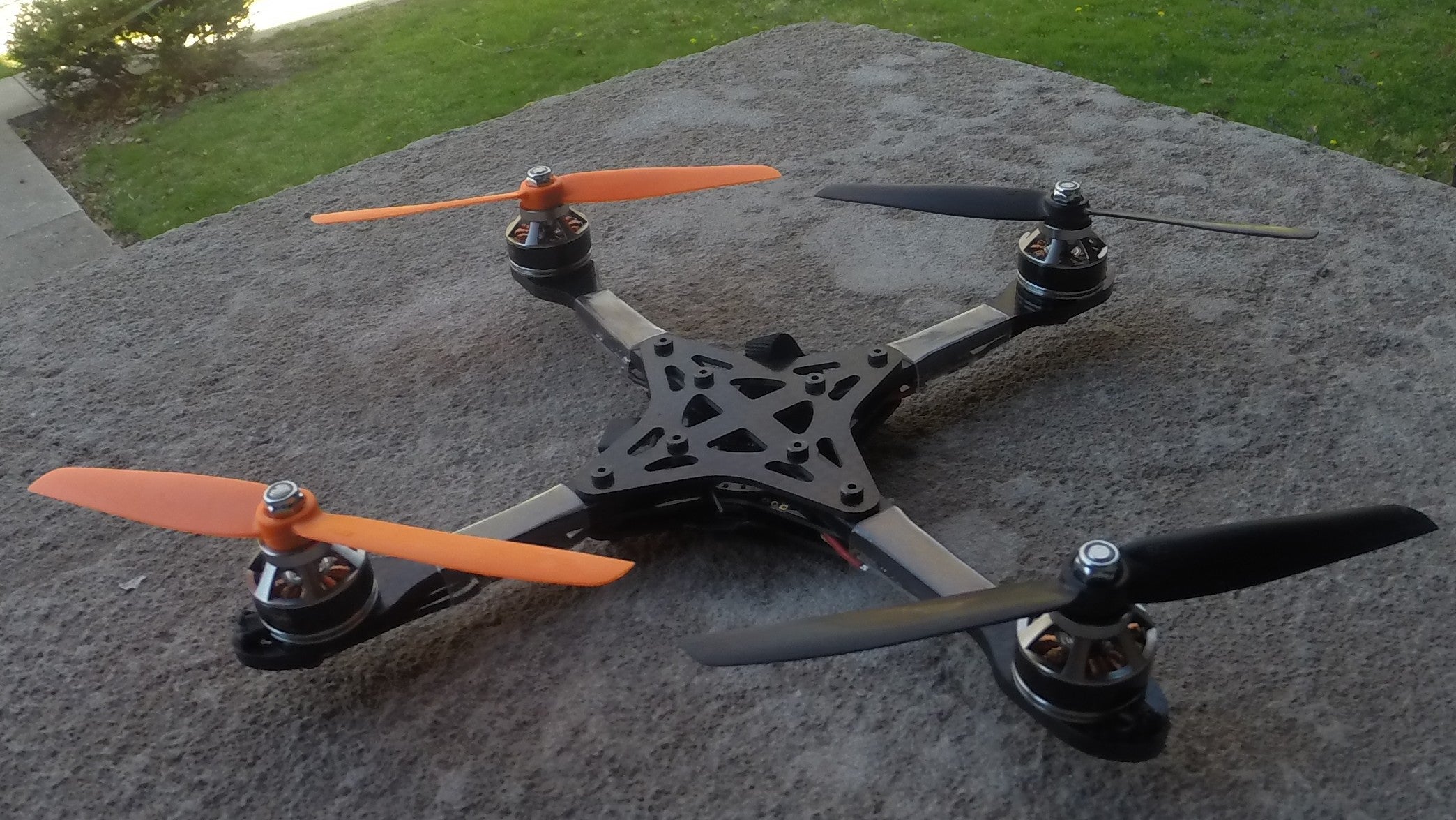
This is my third WarpQuad 230 build.
- My first WarpQuad was built with all of the standard WarpQuad parts as mentioned on the WarpQuad thread. I eventually sold it, because I had a second frame, and really liked the KISS ESCs.
- The second WarpQuad was an attempt to be as clean as possible with a standard flight controller (the Naze32). That build log can be found here with updates here.
The goal of this next WarpQuad build is to be even cleaner and to make the carbon fiber really shine (carbon fiber is so pretty!).
I also have a tendency to go out of my way to something that no one else has done - which, if you've been following the WarpQuad thread, it'll be apparent.
Parts List
- WarpQuad 230mm with 5mm thick arms
Stronger than the original WarpQuad, which has only 4mm thick arms. This also allows me to do a bit of sanding on the arms, and not worry much about diminishing the structural integrity of the arms. - MotoWii Flight Controller
All in one PDB: 8-bit Multiwii Flight Controller + Power distribution - 18A KISS ESC v1.1
- T-Motor 2206 2000kv Motors
- M3 Nylon spacers 4mm height, 8mm outer diameter
This is just a shadow taller than the USB port on the MotoWii. Normally, I would have used prop spacers, but two prop spacers are 6mm tall, and that's 2mm too much. - Low profile socket head cap screw M3 x 20mm - Black Steel
Personal preference on these. The important bit is just the 20mm length. - Polyvinlyl Chloride Heat shrink - 3/4" diameter
Most heatshrink tubing is either cloudy, or just straight up opaque. This heat shrink is a little thicker and heavier, but it's very clear.
Preparing The Receiver
Here, I am seeing if the lemon rx will fit between all the arms, 'underneath' the MotoWii. Turns out it fits with plenty of room to spare.

Before beginning, it's important to bind the receiver. I'll be removing the plug on the receiver, as it's extra height I don't want to deal with. Solid light means bound :-) It is now safe to desolder the connector port thing.


Because I want to have the receiver 'underneath" the MotoWii, I soldered the V/G/S wires to the bottom of the board. You'll notice that the V and S wires are switched on the plug, and normally this wouldn't work, but I'm cutting the wires so I can properly make V the red wire instead of yellow.

Just reminding myself of the order of the wires S/G/V. In the picture it looks G and S are incorrectly placed, but the wire are just crossed.

Wires cut. This allows me to continue to use my bind wire. In the event I ever need to rebind, I can still plugin the connector end to the main lemon rx host receiver, and temporarily solder the ends to the corresponding wires on the satellite receiver. The red and yellow wires will be reversed on this build, because my cables for some reason were built backwards (yellow is supposed to be red, and red is supposed to be yellow)

Connector de-soldered so the entire thing will fit between the 'bottom' of the MotoWii, and the top WarpQuad center plate.

Receiver soldered to MotoWii and testing fit again, just to be sure. I used doubled sided foam tape to secure it in place.


Preparing The Frame
Now for proper colored bolts

Have to sand down the edges of this hole so that the motor wires can safely go through it without worry of being severed. The motor wires are very snug, and just barely fit.


Attaching Motors
Attaching the motors + arms to the center plate


Flip it over - I knew those motor boxes would come in handy for something (they prevent the bolts from falling out).


Previewing what the top plate will look like, and checking remaining length of screws.

Bottom Plate and Battery Strap
I forgot to order the nice thin velco straps from soma, but luckily, I had some extras laying around. Here is how I like to secure the battery. It's a tight fit when only giving yourself 4mm of clearance and there is a mini-b-usb connector in the way. I actually have some micro-b usb connectors, but the pin spacing is different, so I couldn't swap them out.


ESC Prep
I didn't have any of that super thin double sided foam tape, so I decided just to use eletrical tape, and hope that the ESCs will be secured in place by the heat shrink and the tension from the wires on both sides


ESC Soldering
TL;DR: I think the soldering pads on everything were too big, except for the signal pads.
It was weird working with so small of wires. It was also weird to have such large soldering pads on the MotoWii. The signal pad was just the right size, but the +/- pads were just huge, and I had a hard time getting heat through them at 250 degrees C. I also feel like the larger pads on the KISS escs made soldering more difficult in that I more incorrectly judged the length of wire I would need. With the v1.0 KISS ESCs, the solder pads are smaller (I have these on my other WarpQuad), and it was juuust enough to make a connection. With the 1.1, there were times where I felt like I was just dealing with too much solder.


Battery Connector Attachment
Fitting the XT60 in to a 4mm space requires LOTS of sanding of the connector. I actually had to sand down two connectors, cause when trying to solder the first one, the iron burned a good chunk of the plastic as I was trying to figure out a good approach to get the connector to attach. I also had to turn up the heat on the soldering iron pretty high. 425C, as apposed to my normal 225-300C depending on the solder. I used some liquid electrical tape to cover up the exposed connectors on the inside portion of the connector.


Motor Direction
Once powered, the quad has to flip over, and I have to test motor directions. All motors should spin into the center of the quad. I only had to change two of the motors direction (which is great, and means that I soldered all the motors the same way!)
Here is what it looks like with the heat shrink all .. shrunk.


Last Touches / Other Details
4mm Spacers. make the bottom layer thinner than the top / arm layer.


The purple on the bottom looks really nice, but due to using 4mm spacers, I'm going to need to sand down all the 20mm bolts down to 18mm. Because the bolts are too long, I had to add spacers around the bolts near the battery to increase the amount of surface area in contact with the battery. Still not ideal, but will be solved with sanding the bolts.

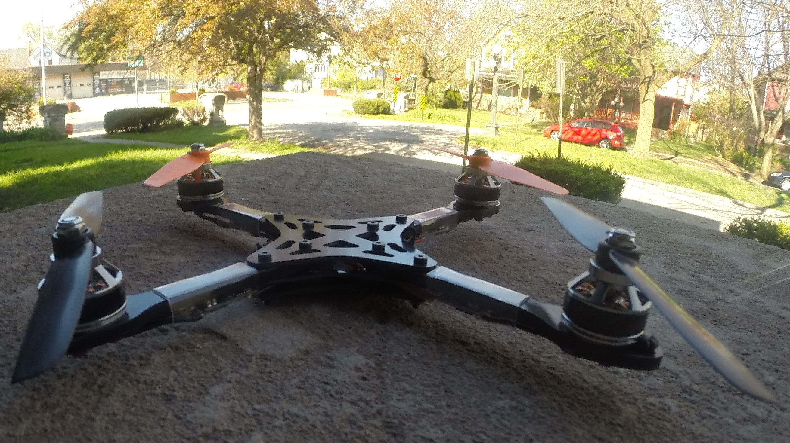
Nearly Finished - just need to sand all the bolts and do maiden flight.


...
DONE :-)
I love building things. :-)

Gfy: https://gfycat.com/AdeptPleasingBat
MotoWii MultiWii Changes
Uncomment:
Code:
#define ONESHOT
Find lines similar to, and copy paste the following.
Code:
      #define FORCE_ACC_ORIENTATION(X, Y, Z)  {imu.accADC[ROLL]  =  -X; imu.accADC[PITCH]  = -Y; imu.accADC[YAW]  =  -Z;}
      #define FORCE_GYRO_ORIENTATION(X, Y, Z) {imu.gyroADC[ROLL] =  -Y; imu.gyroADC[PITCH] =  X; imu.gyroADC[YAW] =  -Z;}
Only thing left to do is to get some HQ 6045 props, and make a video :-)
I should have a 12:1 thrust to weight ratio with a 4S battery.


Log In to reply
But yeah, It took about a week and a half, once the first parts started coming in.
I get 6045 props in the mail this thursday, so I'll put those on with 4S, and post my PIDs when I'm done :-)
Log In to reply
Log In to reply
Log In to reply