Hey Flitefam,
I've always wanted to put lights on my rc planes but not ordinary lights, just like in real life,but, I decided rather than buy one and install it, why don't I design and make one,but later on I realized I didn't even know what the navigation lights signified and how pilots utilize them for safety and visibility.
So in this write-up I'm first going to educate you on the various types of nav lights and what they signify, then we're gonna make a small prototype circuit on a breadboard to learn the circuit connections and in the next part we are going to solder the circuit onto a PCB.
But, before I start ,I have already made a video on this topic ,so if your not into comprehension, feel free to watch the full video given below and don't forget to subscribe to my YouTube channel as I have lots of exciting stuff coming soon ,cheers
Significance of Airplane Navigation Lights
Airplane navigation lights serves a purpose of giving information of the airplanes direction, position and status.It enhances the safety of the aircraft by informing the airplanes position and heading to on coming traffic,when in the air or on the ground.It is incredibly helpful in times of low visibility.
Types of navigation lights and what they signify.
There are presumably two types of lights, the constantly ON lights and the ones that flash known as strobe lights.
Constantly ON lights
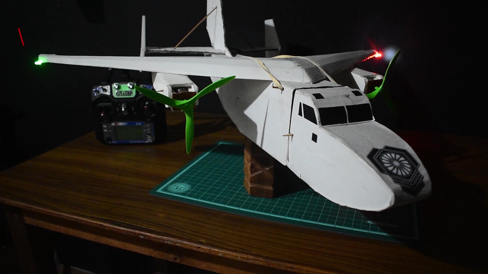
There are three primary constantly ON lights,on the left or port-side wing is a red light,and on the right or starboard wing is a green light ,towards the aft or tail of the airplane is a white light,these lights are known as position or navigation lights and these signify the left and right wing as well as the rear of the airplane to incoming traffic
Other constantly ON lights include landing lights ,located on the leading edge of the wing and on nose wheels,which help the pilot see the runway during takeoff and landing, also present on the vertical stabilizer are logo lights which illuminates the logo of the company or the airline. These lights can be switched on and off if required as they are not crucial to the navigation system.
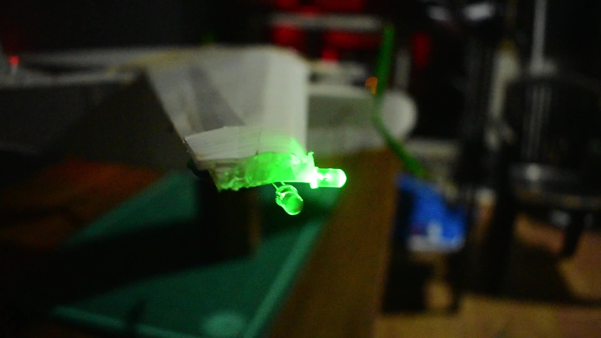
Constant green light on the right wing

Constant red light on the left wing
![]()
Logo lights
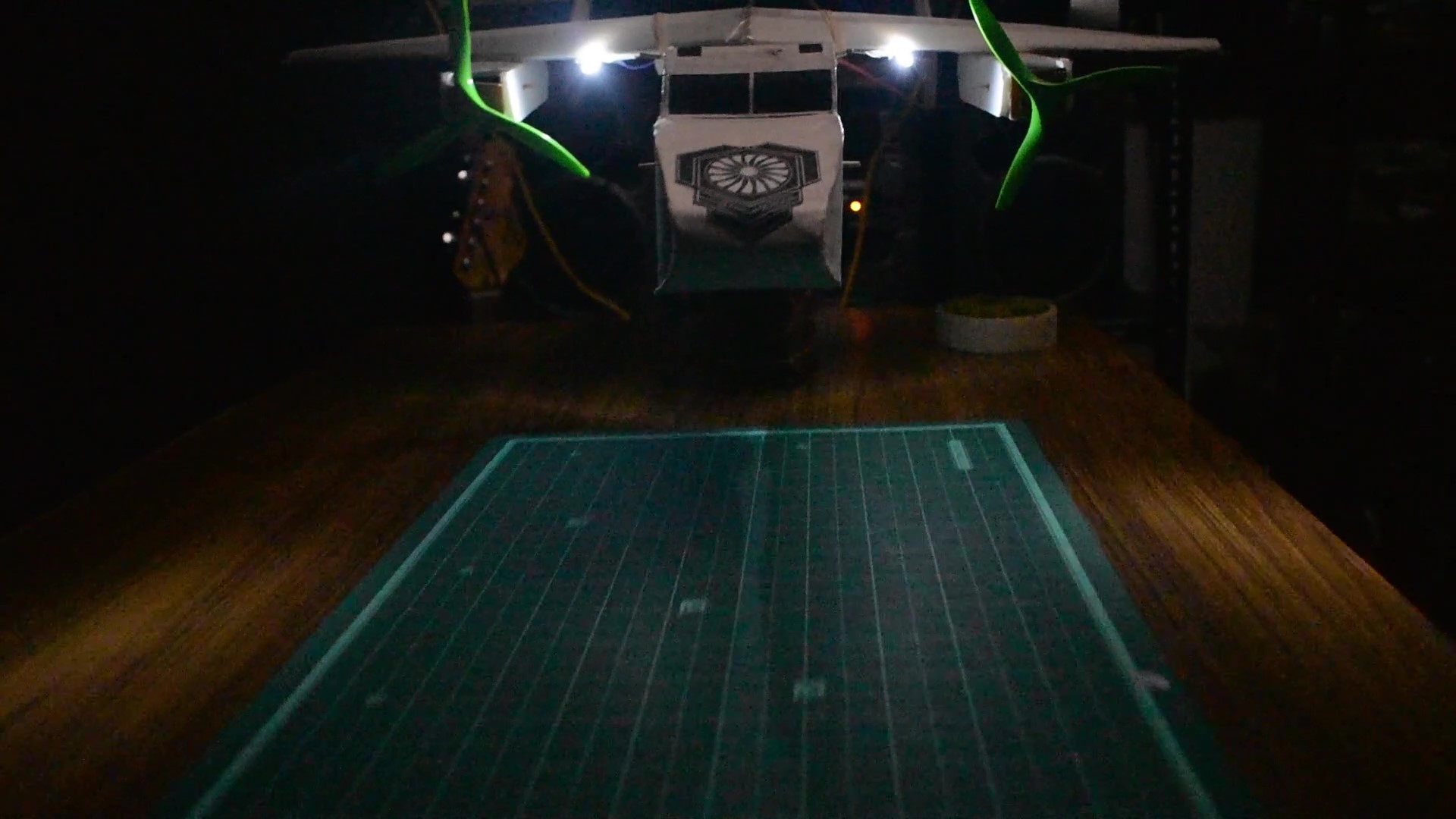 Landing lights
Strobe/flash lights
The lights that flash are known as strobe lights, and on both the wings and on the tail are 3 white strobe lights that are known as anti-collision strobe lights and hence serve that purpose. There are also two red strobe lights on the top and the bottom of the aircraft which alert the ground staff that the airplane engine is ON,and thereby they keep a safe distance from the engine inlet.

White strobe lights
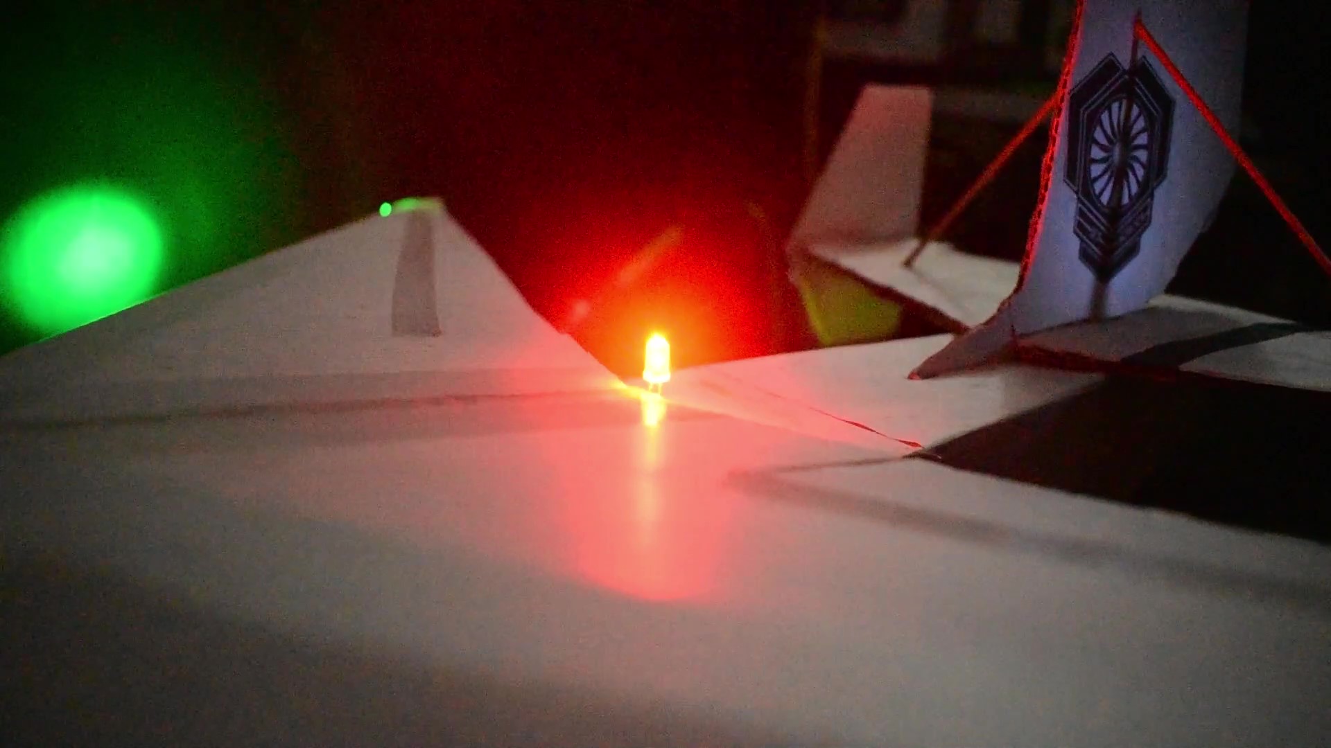
Red Strobe/Beacon light
So that is the basic navigation light system on an airplane, the number of lights may vary depending on the size and type of aircraft.
Electronic Parts Required
1.So the first thing your going to need is a set of resistors the reason I recommend a set and not specific resistor values is that you will have the ability to test the circuit with different values or resistance and set the circuit according to your liking,I'll be discussing how to do that in later parts of the article.
2. 555 timer IC
3. Breadboard
4. Diode
5. 10uF capacitor
6. LEDs
7. Jumper cables or wires
8. 5-12v Power supply
Phase-I
Circuit Prototype
On the breadboard in the middle section all the columns are connected and these vertical strips are called terminal strips,while on the outer sides the rows are connected and are called bus strips,mainly to supply power to the board, with that in mind lets connect the circuit.
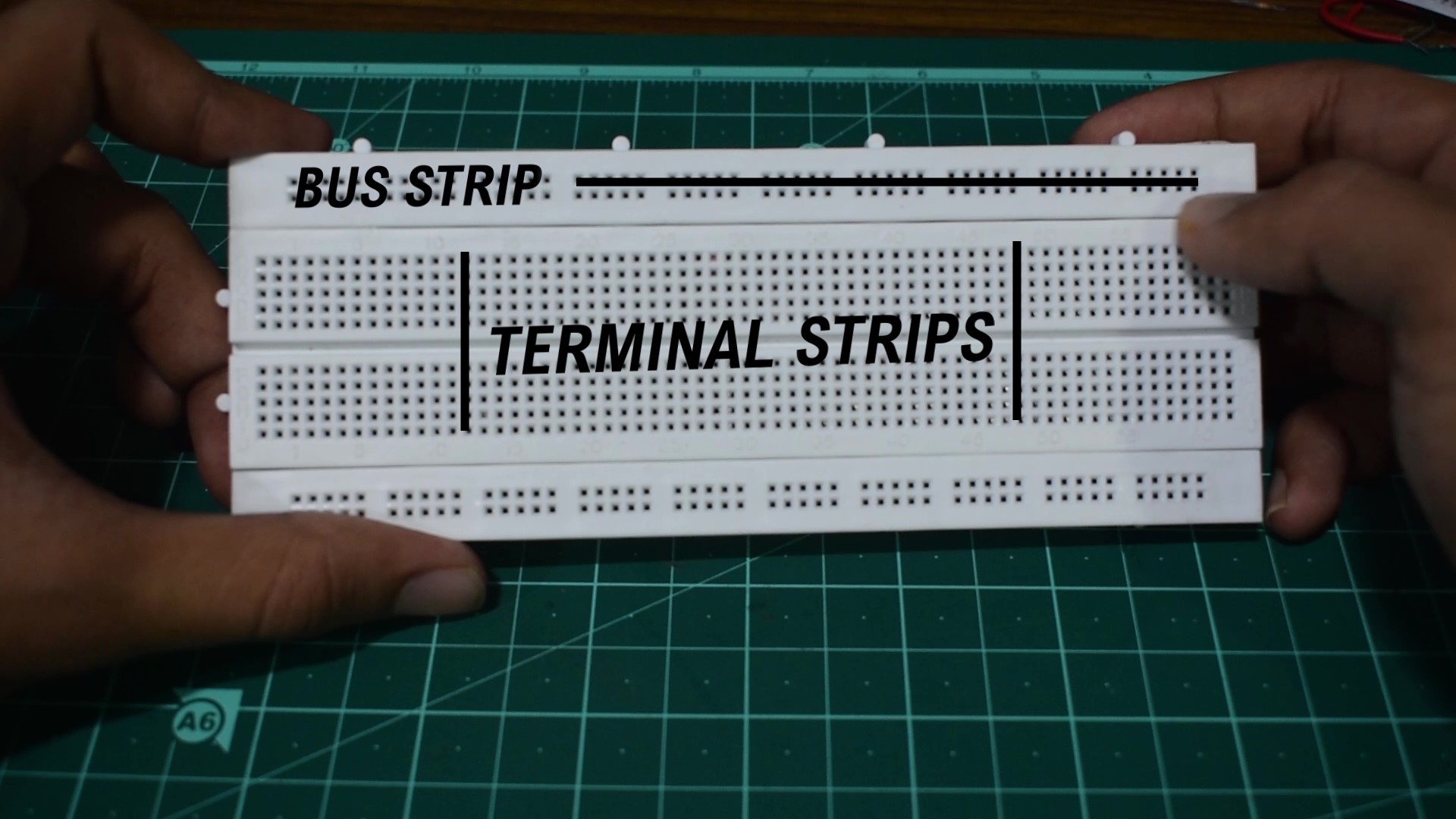
Breadboard Layout
Since the circuit is based around the IC lets first connect the 555 timer IC ,insert it into the breadboard in away in which the small notch is facing towards your left.This is an 8 pin circuit in which the pins are numbered 1-8 from the bottom,in which pin no: 1 is your ground while pin no:8 is your Vcc or voltage input. That's pretty much all you need to know about this IC for this circuit, if you wish to learn all the pins, you can get a lot of pin diagrams on google.
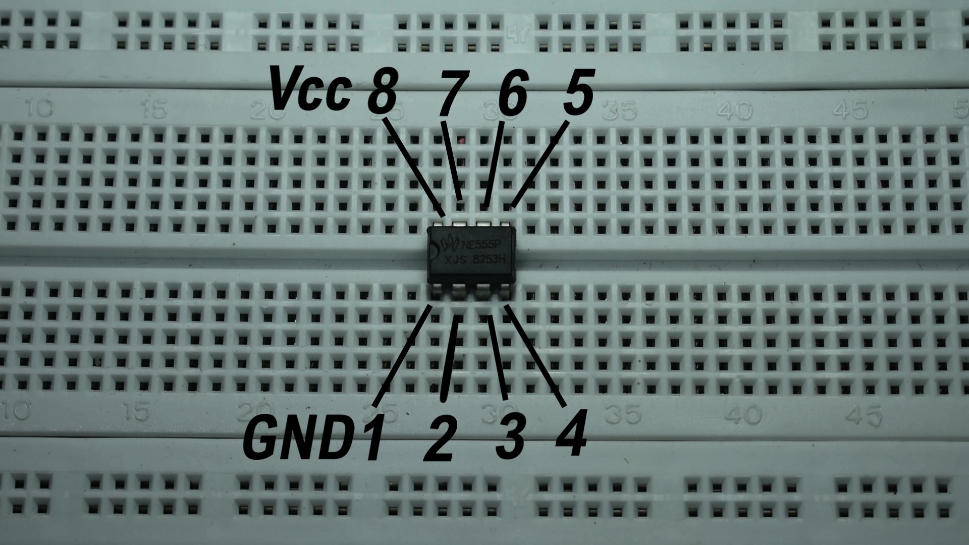 555 timer IC pin Layout
Now we're gonna make a series of connections between the IC pins:
1.First use a wire to connect pin no: 1 ,ie ground to the bus terminal.
2.Secondly connect pin no: 4&5 with a small wire.
3.Similarly connect pin no: 2&6.

Connections between the IC pins
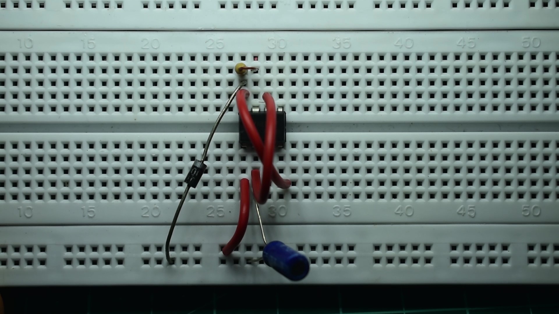
Now let's connect the electronic components,
The first component is a diode,in this circuit the diode prevents the IC from blowing up,when reverse polarized,meaning when the battery is connected incorrectly.The diode does this by acting as a open switch during reverse polarization.
4. So connect the cathode signified by a white strip to pin no: 8 while the anode goes to the bus strip.
5 .Then take your 10uF capacitor and connect the positive terminal to pin no:2,and the negative to the bus strip.
The next components are the resistors,these resistors are determine the LED characteristics ,I'll go in depth about that after we connect the circuit.
6. Connect resistor R1 the highest value resistance ,a 220k resistor to pin no:s 8&7,
7. then connect resistor R2 ,a 10k mid-value resistor to pin no:s 7&6
8 .Finally connect resistor R3, 100E resistance to pin no:3 and to another column in the terminal strip
9. Next connect the positive terminal of the LED to the bus strip, while the negative goes to the other end of resistor R3.
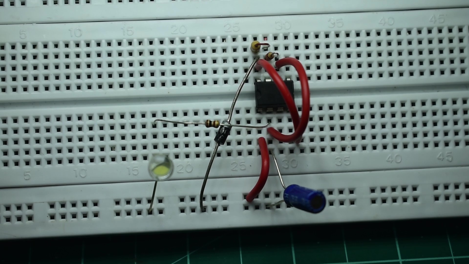
Strobe light only circuit
Now connect the power supply,and it works,
10. Now take another 100E resistor and connect it to pin no: 1 and to the terminal strip then connect another LED just like before and Wala both the strobe light and the constant light work perfectly.
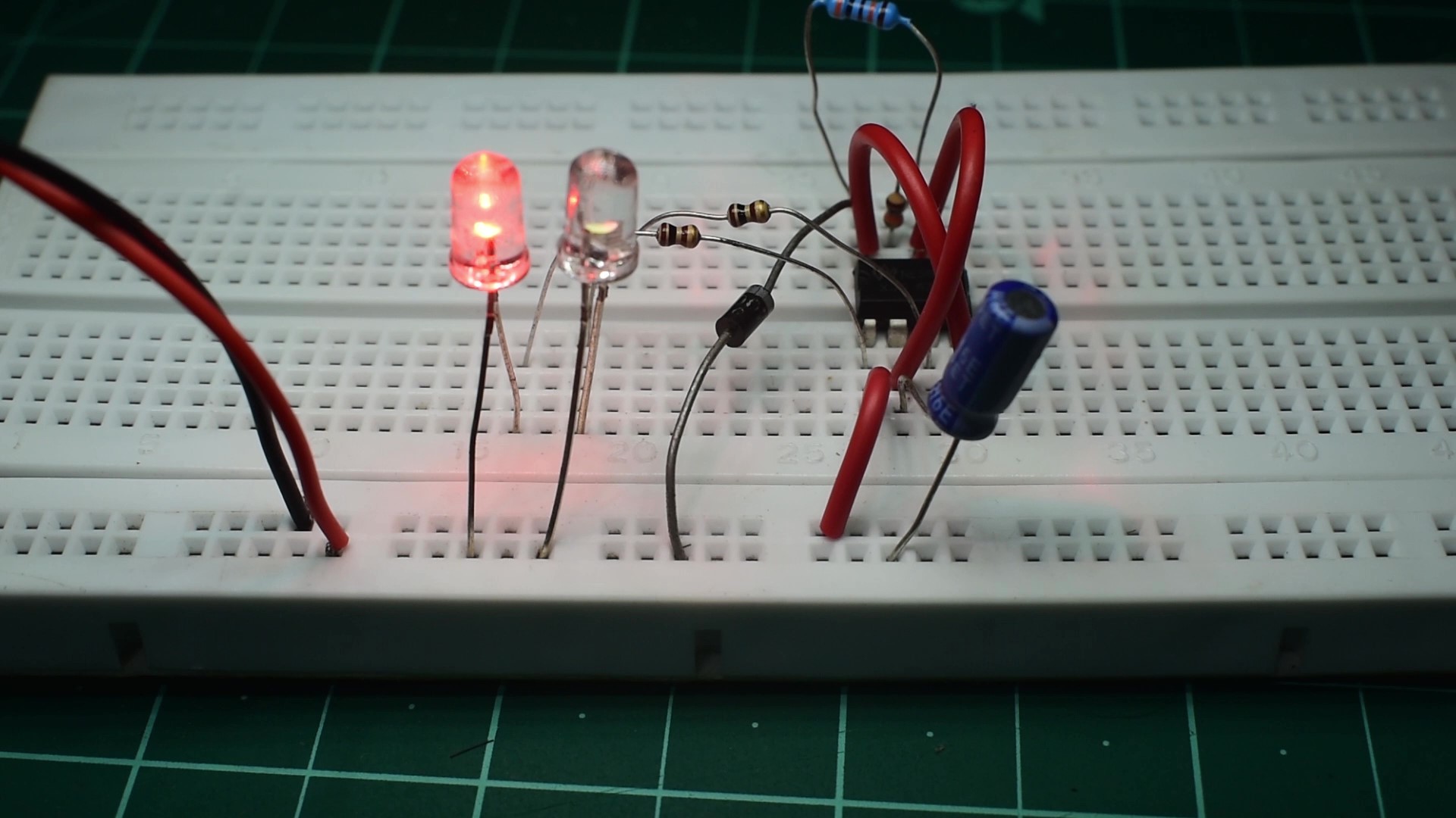
Completed Circuit,Strobe+Constant
As I mentioned earlier that the resistor values determine the characteristics of the LED ,resistor R1 determines the time duration between two successive blinks ,ie the time duration that the LED remains off,so increasing this value can increase that time duration. Resistor R2 determines the time duration that the LED remains ON,ie how long the LED will glow,while R3 only varies the brightness of the LED.
I experimented with a few combinations and found that the most similar to a real airplane is when
R1-330k
R2-10k
R3-100E,
this is just my preference, you can change it according to how you like.

Recommended Resistor Combination
Conclusion
So that's the end of Phase-I,where we learned what airplane nav lights signified and made a circuit prototype.
This circuit design is meant to be as simple as possible and it does have its incapabilities, for example it cannot imitate the timing between the red strobe light on the fuselage to the white strobe lights on the wings ,as these flash when the other turns off and I think requires a second ic as the timing is opposite to that of the existing strobe light, so if possible I plan on making a improved version, which is more compact, has all the typical nav lights and is more stable in terms of voltage. Hope you guys enjoyed this writeup, also stay tuned for Phase-II were we take this circuit and solder it onto PCB, so that it will be compact and light enough to be installed on an rc airplane.

Thank you for reading my write-up,Hope this was helpful!


Log In to reply
Log In to reply