Cheap Power Supplies for Battery Chargers

by shermanhartman | October 22, 2014 | (10) Posted in How To

When you get into flying and driving RCs, things tend to get expensive. Because of this, I'm always looking for a cheaper way to do things, which is why Flite Test is so awesome.

When i got started in RC flying, I ordered the cheapest power supply i could find for my battery charger. When i tried to charge 4 cell batteries, it would overload the power supply. So i had to charge my 4 cells slowly. I decided to do something about it.

This tutorial is really only cost effective if you have a computer that you're getting rid of, or have access to junk computers. Watch out for your local dumpster day!


WARNING! Computer power supply units have massive, very powerful capacitors inside of them. They can give a pretty nasty shock if you are not careful. This should not be attempted by anyone who doesn't have a basic knowledge of electronics. If you have any concerns or questions, ask them below BEFORE you open up your PSU. Now, lets get started!


Materials that you need:

  • PSU out of a computer
  • XT-60 Panel Mount Kit
  • SPST Switch (optional)
  • Power Cable for PSU
  • Small breadboard (optional)

Tools/supplies that you need:

  • Soldering iron
  • Solder
  • Flux
  • Wire cutters
  • Wire strippers
  • Medium/thin CA
  • Phillips screwdriver
  • Drill with large bit
  • Dremel
  • Multimeter/voltmeter
After you've gathered all the supplies you need, you can get started. Remember, never touch any bare traces/bare wires even when the power is disconnected. And DO NOT apply power to the unit with the case open!


First thing you need to do is make sure that you have enough output power on the 12 volt rail. On this power supply, i have 18 amps, which is plenty for my battery charger.


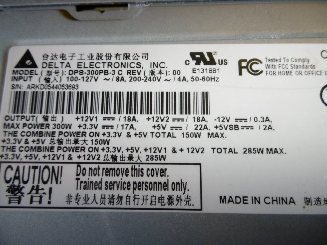
Now, you need to know which color wires go with each power rail. One color wire corresponds with each voltage. The most common color for +12 volts is yellow. Black is always ground. If you aren't sure, you can turn on your power supply, and check each wire color with a multimeter. To turn on the power supply, you have to find the Brown wire, and connect it to a ground (Black) wire. Now you can check each wire color's voltage. You can cut all of the connectors off of your unit at this time, but leave enough wire to work with. You can always make it shorter later.


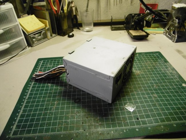
Once you know each voltage, write them down, and start taking the case off of your unit, keeping track of all the screws. Unscrew the fan from the case at this time also.


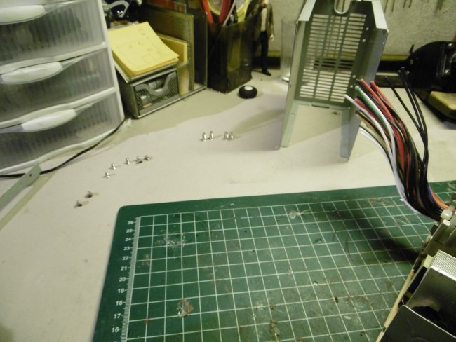
Cut all the zip ties that hold the wires in place inside the unit.


Unplug your fan from the unit, and take it out of the case. Then, remove the power wire from its track. We are relocating the fan to the outside of the case, just to make more room.


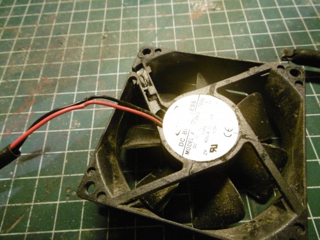
Route the power wire through the fan grill so that it won't be pinched anywhere when you re-attach the fan.


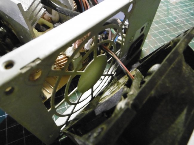
Plug the fan back into its connector, as seen here.


Make sure the connector isn't going to pull off of its pins.


Now screw the fan back onto the case from the inside.


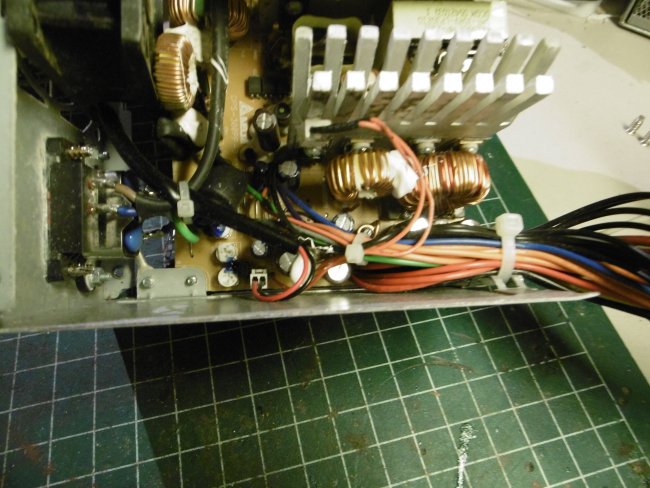
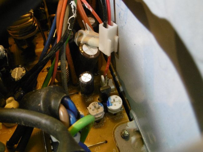
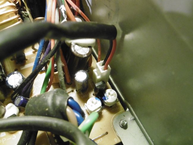
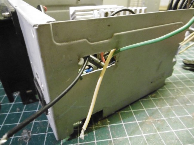
Next, untangle the wires and sort them by color. Notice the group of different color wires on the right. The only wire we need from this group is the power wire, which is brown.


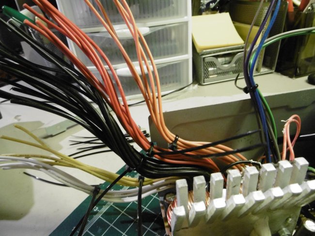
We only need the Yellow, Black, and Brown wires. Cut all of the other wires as short as you can, making sure the bare end isn't going to touch the side of your case, or any other components on the board.


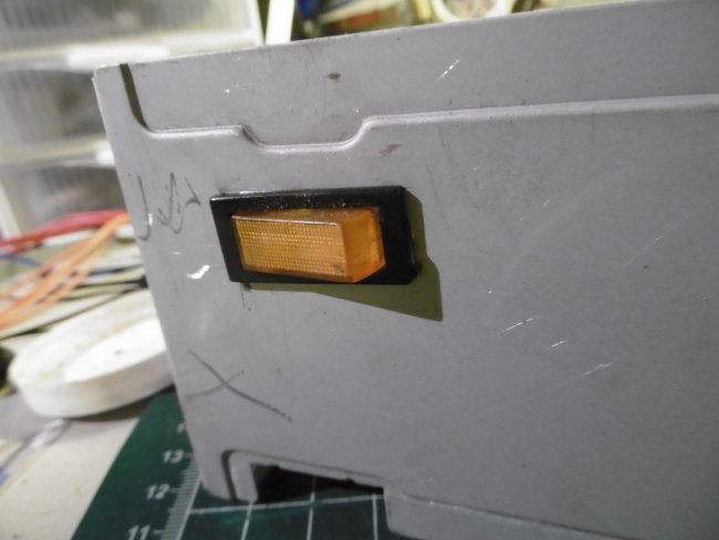
Now lets move to the switch. I'm using a lit SPST switch. It works the same as a normal SPST switch, but when its on, it lights up. I used one of my +12v wires to power the light on the switch.


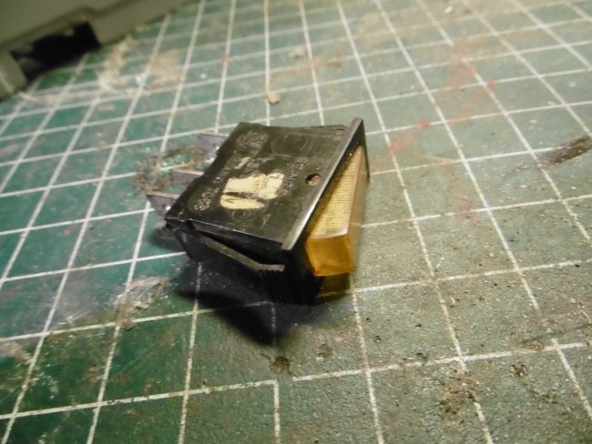
Take measurements of your switch, and mark out a spot where there is plenty of room on the inside of the case for wiring. You don't want components touching each other inside the case.


Test fit your switch before you start soldering!! It will save you time in the long run.


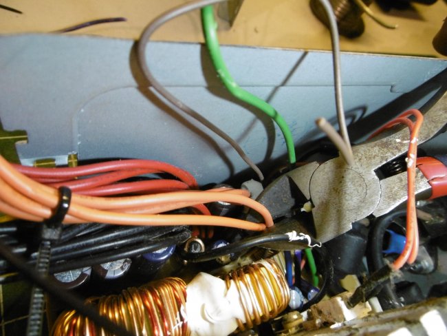
Run a ground wire and your brown wire through the hole. The yellow wire is for the light on my switch. Put shrink tubing on your wires at this step if you prefer.


Solder the wires onto the terminals of the switch. I chose to skip the shrink tubing, since it was in an enclosed, grounded case.


Insert your switch into its mounting hole.


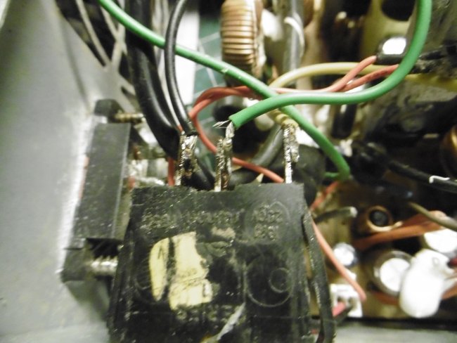
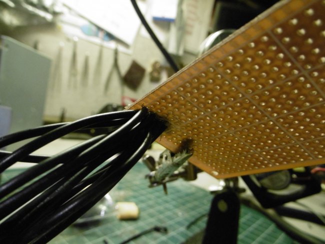
Now its time to start soldering. In order to get as much amperage as advertised from your PSU, you need to combine all off the ground and +12v wires. You need to combine all of the +12v wires and all of the ground wires to get the maximum amprage possible from you unit. For the ground, since there is about 15 wires, i like to use a breadboard. Put all of your ground wires together and solder them into one large connection. If you chose to skip the breadboard, simply solder all of the ground wires together.


Do the same wit the yellow wires, but without the bread board. Then, add some wire to each solder lug so that you can connect it to a plug later. (That solder lug for the ground looks horrible!)


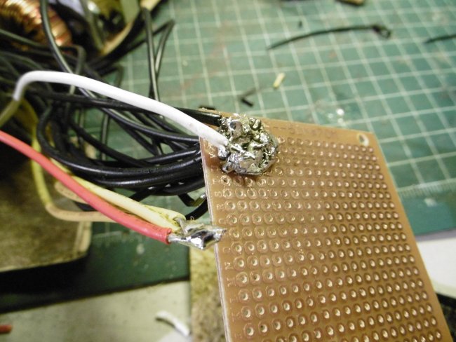
Cut your breadboard off so its as small as possible. (An even closer look at that ugly solder lug! Eww.)

Wrap both the breadboard piece and the +12v wires with electrical tape. Make sure all of the bare metal is covered.


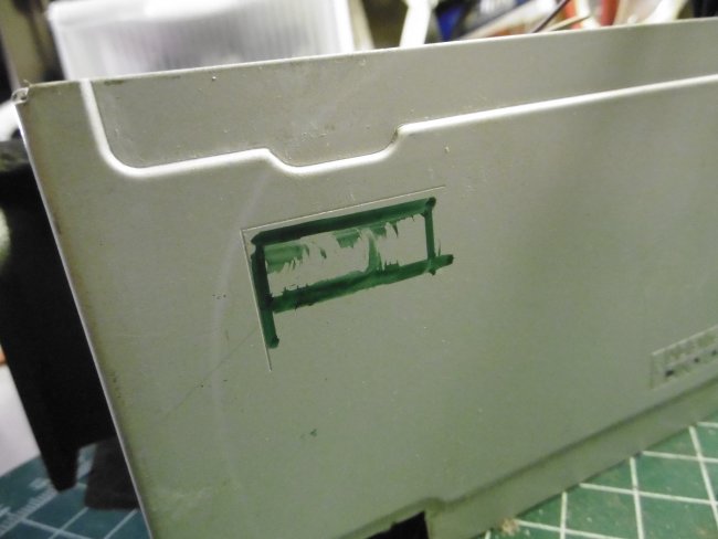
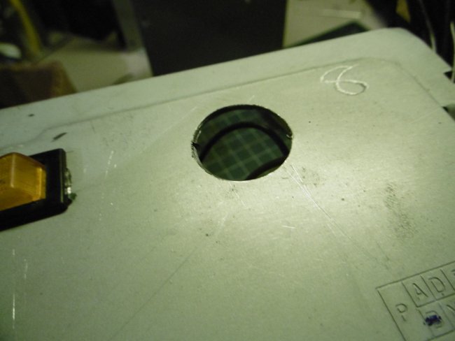
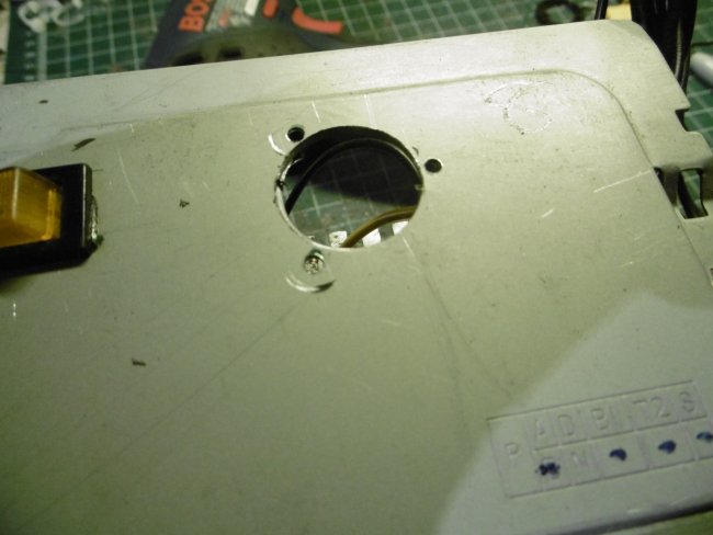
Now we can move on to the panel mount. Find a drill bit the same size as the panel mount. I used a step bit.


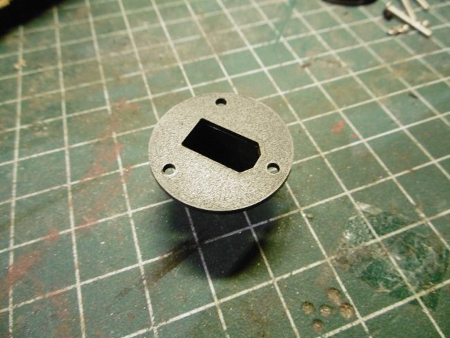
Drill your hole, and make sure its clean of any burs.


Test fit your mount. If it fits, use a marker to mark the 3 holes around the mount.


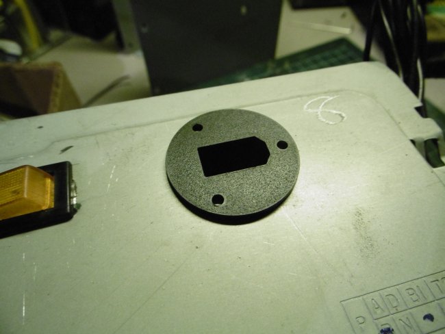
Drill these 3 holes for the mounting bolts.


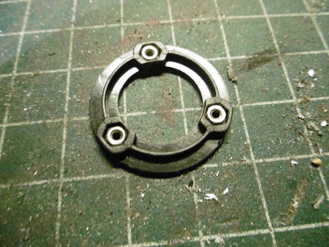
Using a dab of medium or thin CA, glue the 3 nuts into the back side of the mount. This makes installing the bolts much easier later.


Thread the wires through the back connector and solder on you ground and +12v wires. If you want to use shrink tubing, put it on before this step. As you can tell, i again, chose to skip the shrink tubing.


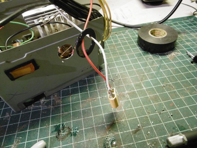
Thread your connector through the mounting hole. Line the back mount up with the mounting bolt holes.


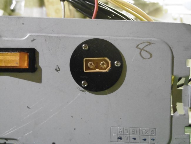
Mount the connector into the panel mount using the included grub screws.Try and make sure the connector is level with the edge of the mount for a neat look.


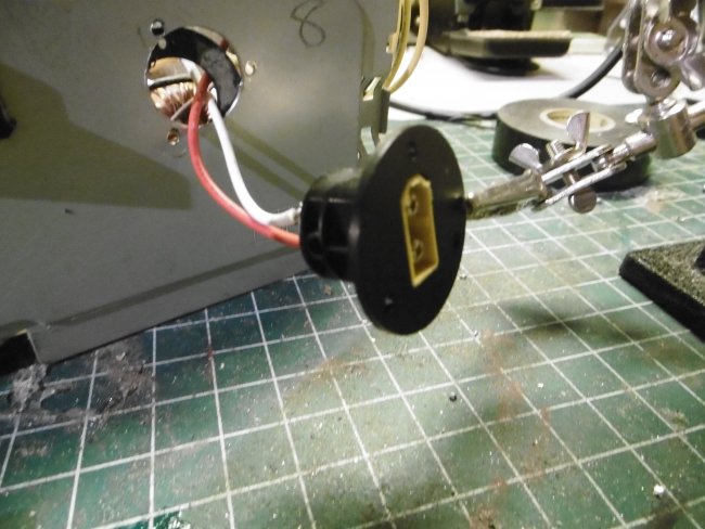
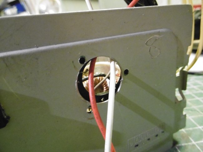
Install the bolts using your screwdriver. (Aww man, my connector is crooked...oh well)


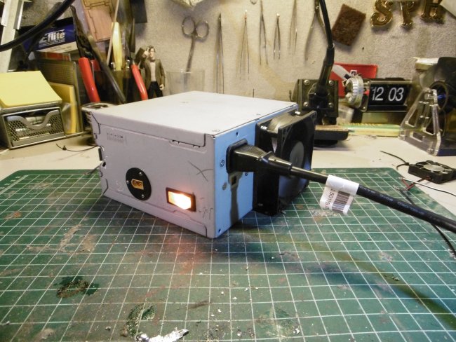
And youre done! Put the cover back on and test your unit. When you turn your switch on, your fan should spin up. If the fan does not come on, and you get no power from your XT60, you may have:

  • Used the wrong wire for the power wire on your switch

  • caused a short somewhere in the circuit

  • used a PSU that didn't work to begin with (there was a reason they were getting rid of that computer. haha.)

Go back and retrace your work if it does not turn on properly.


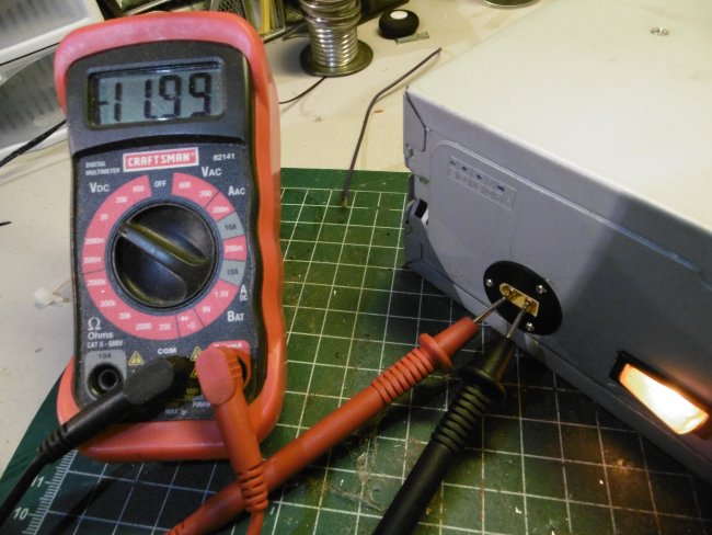
Use your multimeter to check and make sure you have +12 volts coming out of your connector. (I had my probes connected to the plug backwards, which is why it shows negative.)


Connect up your charger and start charging! Thanks for reading! Please let me know what you think. If you have any questions, please leave them in the comments below and i will do my best to answer them! Keep on flying guys!


If you're on Facebook, check out this awesome group that I am a part of. Its called Flitetest Fan Swapables. We hang out, bounce ideas and questions off of each other, and post about our builds. Anyone is welcome! https://www.facebook.com/groups/1418914708327072/

See you there!

Sherman H.

COMMENTS

Gsimpson2g on October 25, 2014
Nice article! I just soldered a Molex connector to the power plug for my charger, and hook it up to my PSU. Probably not the safest, or best route when it comes to charger higher than 3S batteries, but works for me right now. Next time I have a spare PSU though I will be giving this a go!
Log In to reply
shermanhartman on October 25, 2014
Thanks! Its a pretty simple thing. I always used these as bench top supplies, so i thought to myself, why not use it for my battery charger. Haha. It works great.
Log In to reply
Yogenh on October 25, 2014
I will have to work on one for me

Log In to reply
shermanhartman on October 25, 2014
Let me know if you need any help with it!
Log In to reply
Yogenh on October 26, 2014
Will do
Log In to reply
Andre Meyer on October 26, 2014
Great idea and executed wel.

I have had one of these for a while now and its great. I dont know why I did not think of the XT 60 plug on the side. I have 2 points where I connect my alligator clamps. Its back to the drawing board and replacing them with a XT60.

Thanks great idea.
Log In to reply
shermanhartman on October 26, 2014
Thanks!
Log In to reply
alibopo on October 26, 2014
Nice idea, and obviously it works, but I'm concerned by the approach to insulation and termination. I once dismantled a UK mains plug to find the person who had wired the plug had stripped-back the insulation on the wires right back to where the 3-core cable entered the plug. Inside the plug was nothing but bare copper wire; earth, live and neutral, and they wondered why it kept blowing fuses...Sleeving and coverage of exposed wires is theoretically not necessary where there is good permanent mechanical separation of wires, but takes no account of accidental shorts from foreign objects entering the enclosure, or components breaking loose. Safety 'rules' and recommendations have built up over the years as a response to those one-in-a thousand/million accidents that result in catastrophic failures. It may seem pedantic, but unless you can remove it from the base board I'd blind terminate every wire not in use, as opposed to just snipping them off close to the base board. As simple as taping the end with insulating tape, in fact I'd fold the end of the wire over as well to prevent the plastic sleeve from slipping along the wire. I'd also cover the connectors on the lit switch with shrink wrap, or use those nice spade connectors that are designed to go over that kind of connector. You can get them with a fitted plastic shield that completely covers the connector - you find them all over the place in car wiring. That soldering did look very dodgy, and the problem with that is you don't know what continuity there is in the join. The join has to be mechanically good to get the continuity. A 'thin' connecting means more current passing through a small joint resulting in heat - maybe enough to de-solder the join and eventually get a loose end of wire waving about inside your enclosure, ready to short on or across one of those exposed connections elsewhere in the enclosure. The little bread board you suggest just seems to be a means of grouping the wires, but I think a less experienced 'solderer' will probably have problems with wires dropping out as they added more and more wires. I think your other suggestion was better - by exposing maybe an inch of copper wire on every wire in the group, it's easy to twist all these together to form a regular thick, round 'wire'. Apply solder to the whole group, and with sufficient heat the solder flows into the mass of wires making a neat single 'solid' wire. For these bigger joins you need a reasonable size soldering iron, one of those tiny little ones used for electronic components is robbed of heat so fast by the component, the solder starts to cool and set before it spreads. Once you have your 'big wire' it can be trimmed to length and connected to a simple screw block terminal. (This solder method is how they terminate the flex in mains powered clothes irons to ensure the best electrical connection.) A final wrap of insulating tape around the block terminal will eliminate any possibility of a bump knocking the exposed screws on the block into another component that might cause a short. Having grouped the mass of 12v wires to provide the maximum available current I think you need to say that the single wire coming from this group needs to be thick enough to carry this combined current. Maybe obvious, but I think it needs to be said. Regarding your soldering, it really does look pretty dodgy - possibly your soldering iron is too small? Those connections onto the lit switch might not be as good as you think, (commonly known as 'dry' joins) and those little strands of wire sticking out the side... A good solder join should look smooth and 'pearly'- if it looks spiky, ridged, uneven and discoloured by flux, the solder wasn't flowing properly due to lack of sufficient heat. When making this type of connection with larger components and a smaller soldering iron, it helps to 'tin' the end of the wire with solder and then 'tin' the place where the connection is to be made - less heat required for each initial join. 'Tinning' is just applying solder - it shouldn't sit as a blob, but flow and spread into or across the component. With a big enough soldering iron this will be almost instantaneous. Most overheating/melting of components is due to sitting a 'too small' soldering iron on the component for a long time, and having to wait for sufficient heat to build and raise the temperature enough to allow the solder to flow. Tinning ensures you have a good 'join' between the solder and the component, before you even try to connect the components. Then bring the two components together, apply heat and the two little 'reservoirs' of solder flow together ensuring a good electrical and mechanical connection. Having said all that, done right this is a great money-saving tip. Cheers, and thanks for sharing.
Log In to reply
shermanhartman on October 26, 2014
Wow. Thanks for the comment. I wasnt to concerned with the covering of the cut off wires because all PSUs have an overload shutdown of some type. So if there is a short, the PSU just turns itself off, until you reset it. It probably is a good idea to cover the wires, but its a lot of wires to cover. haha. And about my soldering, i was experimenting with a few different things. I did use a small pen for my joints. I haven't purchased anything of good size yet, altough i should. Thats why the ground joint is so sloppy. And I intended to put in that you need to combine all of the wires to get max amperage. I guess i forgot. Ill have to edit that in. And for the solder on the switch, I accidently mixed 2 different types of solder (Leaded and lead free) so it wasn't the easiest to get a neat looking joint. I actually tinned the pins on the switch with leaded solder and then tinned the wires with lead free solder. Normally my soldering work is much neater and nicer than this. Thanks for the awesome comment!
Log In to reply
alibopo on October 26, 2014
Bummer with the mixed solders :) - it really doesn't want to mix. I do have lead-free for plumbing work, but use the standard electrical stuff with the resin core flux for everything else. My lead-free has no flux core so I use a 'nasty' flux paste with those plumbing joins - pretty caustic, and it cleans everything to a shiny finish. Probably not recommended for electrical work... When you get a bigger soldering iron you'll find the joins happen like magic. One touch and its done. Cheers.
Log In to reply
c.sitas on October 27, 2014
A really great read guys.. Both of you are well versed,and say things in a commoners way. I have one point to offer here though. In reference to using plumbing solder and flux for electrical work, It is not recommended at all because ,as mentioned it is really caustic and later down the road it will actually eat the wires and things will grind to a halt. Roisen is the right flux. Never could spell. Anyway ,great article guys.
Log In to reply
shermanhartman on October 30, 2014
Yup. Most flux is acidic, so it will eat pretty much everything. If i do end up using normal flux and solder, i make sure i clean everything off when im finished. But using rosin core solder is definitely the better choice.
Log In to reply
ludodg on January 19, 2015
Sorry if I'm wrong but I have some problems with the wire-colors.
You mention the important BROWN wire but the pictures show a GREEN one.
See picture 10 and 14 where you make the connections with the switch. i clearly can see a black connection on the left, yellow in the centre and green wire on the right connector of the switch.

Offcourse maybe I suddenly could have become color-blind?!?
Log In to reply
shermanhartman on January 19, 2015
You may very well be correct. I'm actually parshly color blind, and green and brown are colors I often mix up. I'll have someone check it, and ill update the article if I put the wrong color. Thanks!
Log In to reply
Ktrpilot on July 27, 2015
This is a cool idea with plenty of room to modify it for your own needs. It would be possible to power more Than one charger off it. One thing to be aware of though is if you have a house/workshop fire and this was discovered weather it was part of the cause or not, your insurance company might not pay out.
Log In to reply

You need to log-in to comment on articles.


Cheap Power Supplies for Battery Chargers