Hey Flitefam,
This is the continuation of the first part where I wrote about what airplane nav lights signify, and showed you a circuit prototype, to make your own DIY nav light module. So in this part where going to take what we learned from the previous article and make that into a compact and lightweight module, so that we can install it in our model and illuminate our airplanes.
But,before I start,I have already made a video on this topic,so if your not into comprehension,feel free to watch the full video given below and don't, forget to subscribe to my YouTube channel as I have lots of exiting stuff coming up,Cheers.
Components and Tools Required
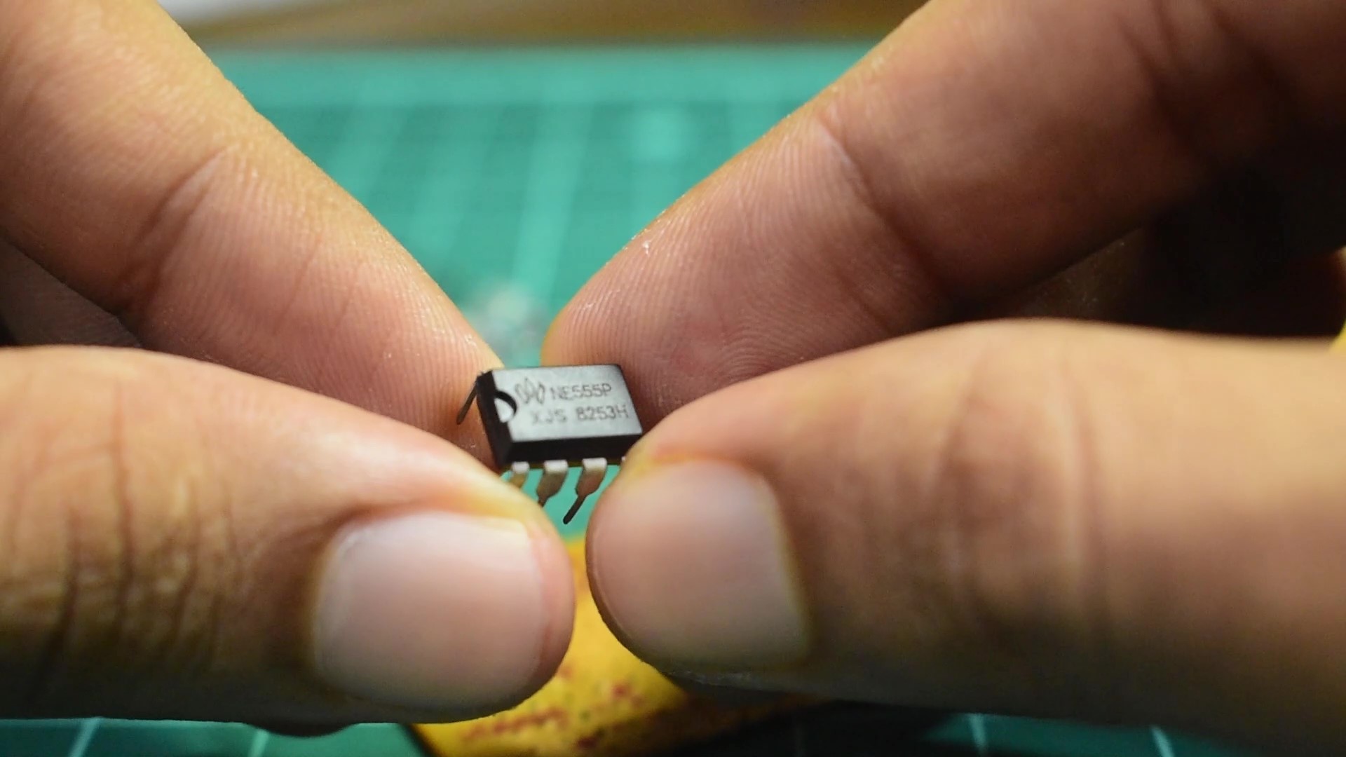
1. 555 timer IC
2. Resistor Set- | R1-330k | R2-10k |R3-100E|(my preference)
3. PCB
4. Diode
5. 10uf capacitor
6. LEDs
7.Jumper cables and wires
8. 5-12v Power supply
9. Soldering Iron
Lets Begin
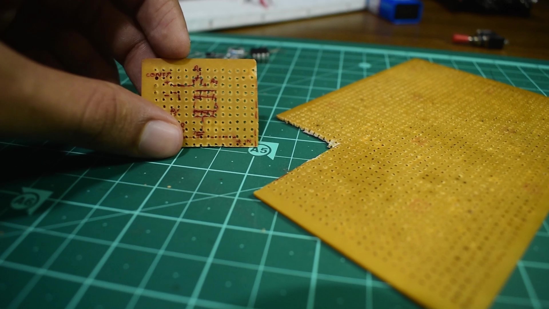
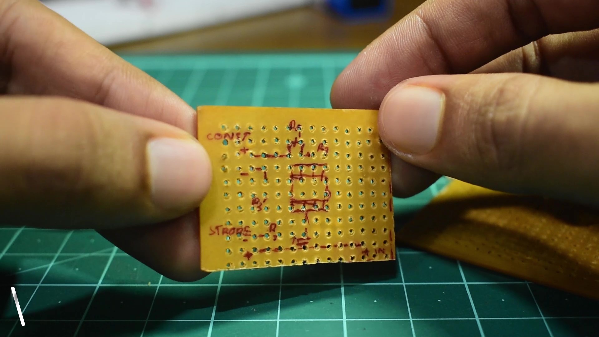
First your gonna need to draw the circuit diagram onto your PCB ,which will help you identify which holes to solder the individual parts to .
Circuit Illustration-https://www.instagram.com/p/CA5frWvg3t2/?utm_source=ig_web_button_share_sheet
After drawing the Circuit diagram you'll also need to cut the PCB in a way that the PCB is small and still has ample room to house all the components. If you have done the steps mentioned above, then lets start soldering on the components.
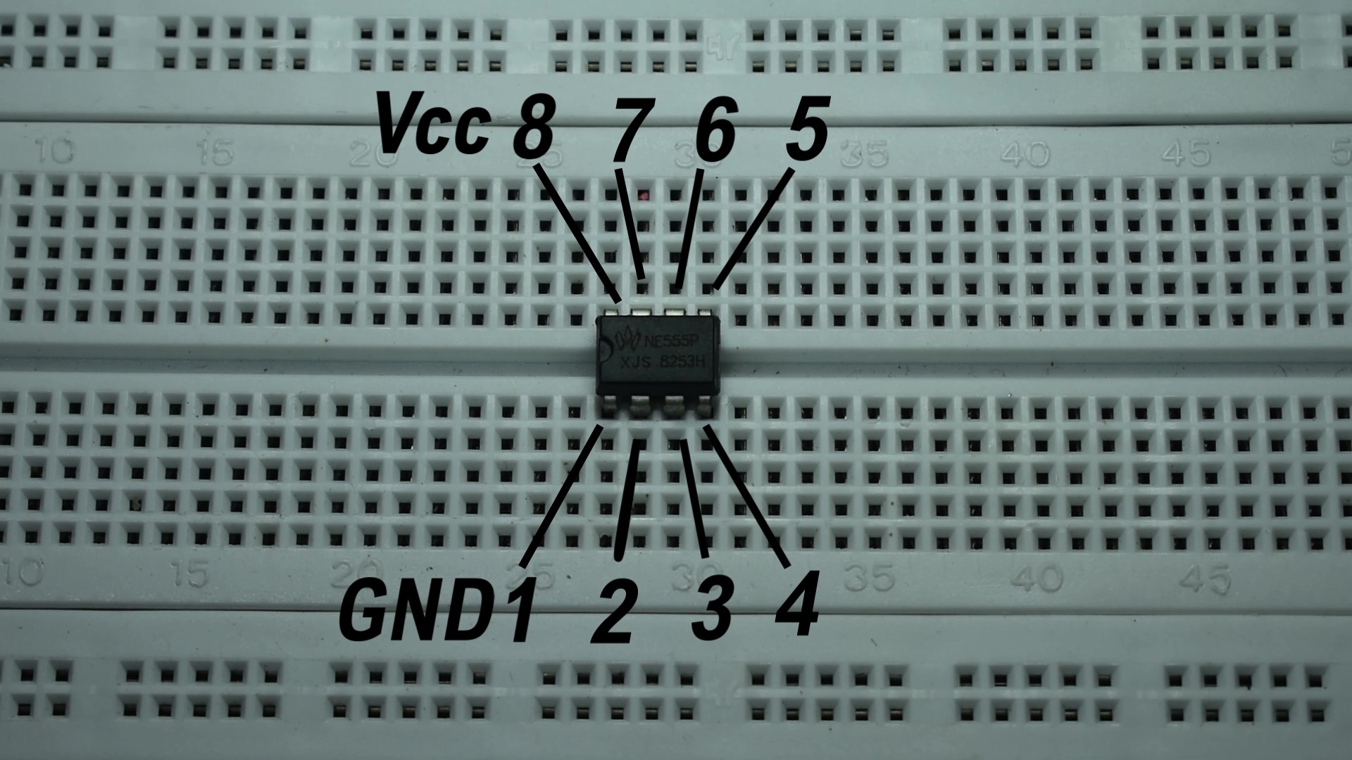
IC pin Layout
Soldering the Components
Component 1:555 timer IC
We are going to insert the IC on to the PCB in the center in such a way, that the small notch on the IC is towards your left hand side
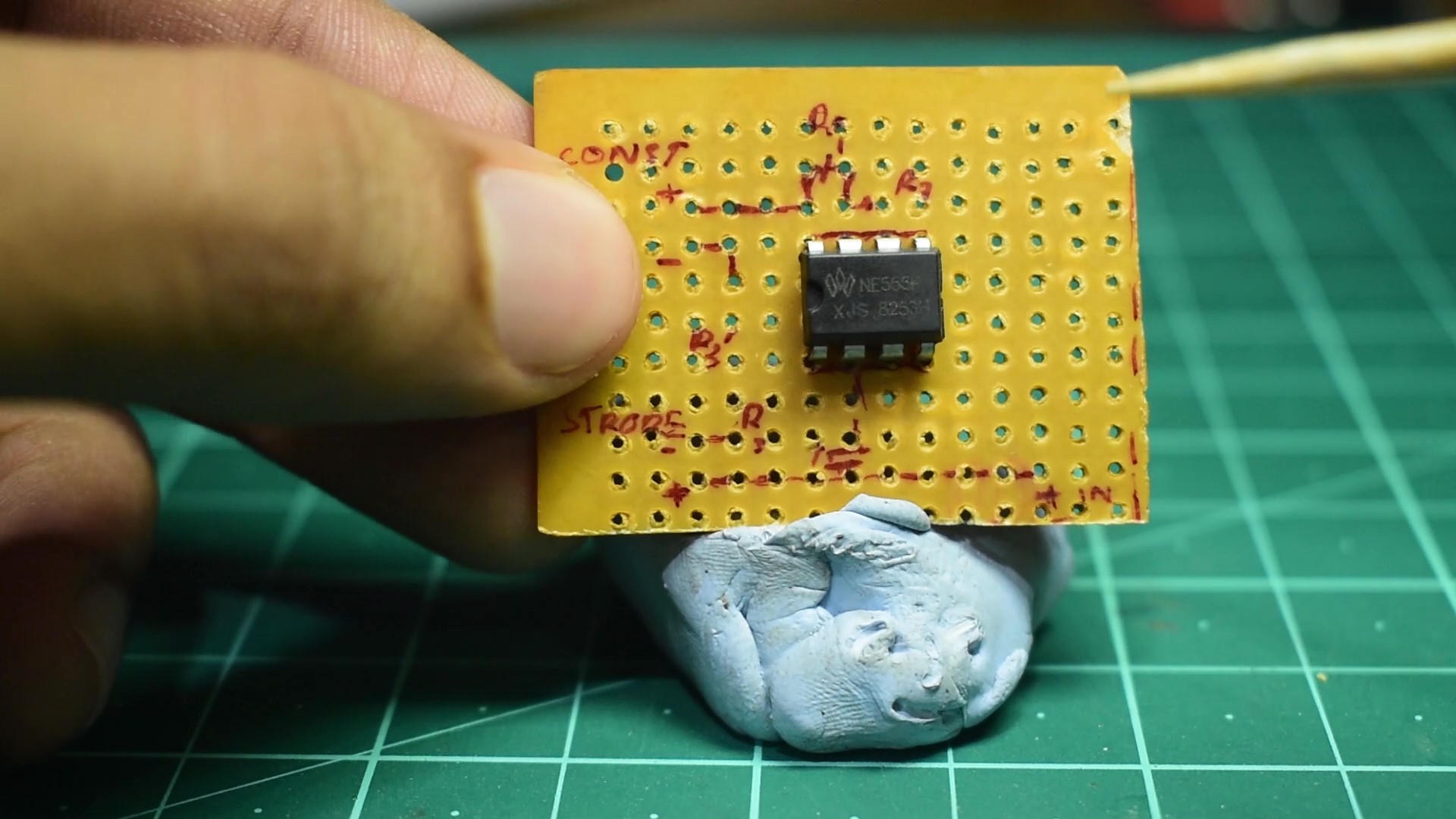
After inserting the IC,we'll need something to hold the PCB while we're soldering ,so for that I'm going to be using "blue-tack", a sticky clay, you are free to use anything that can hold it firmly,like a soldering stand.
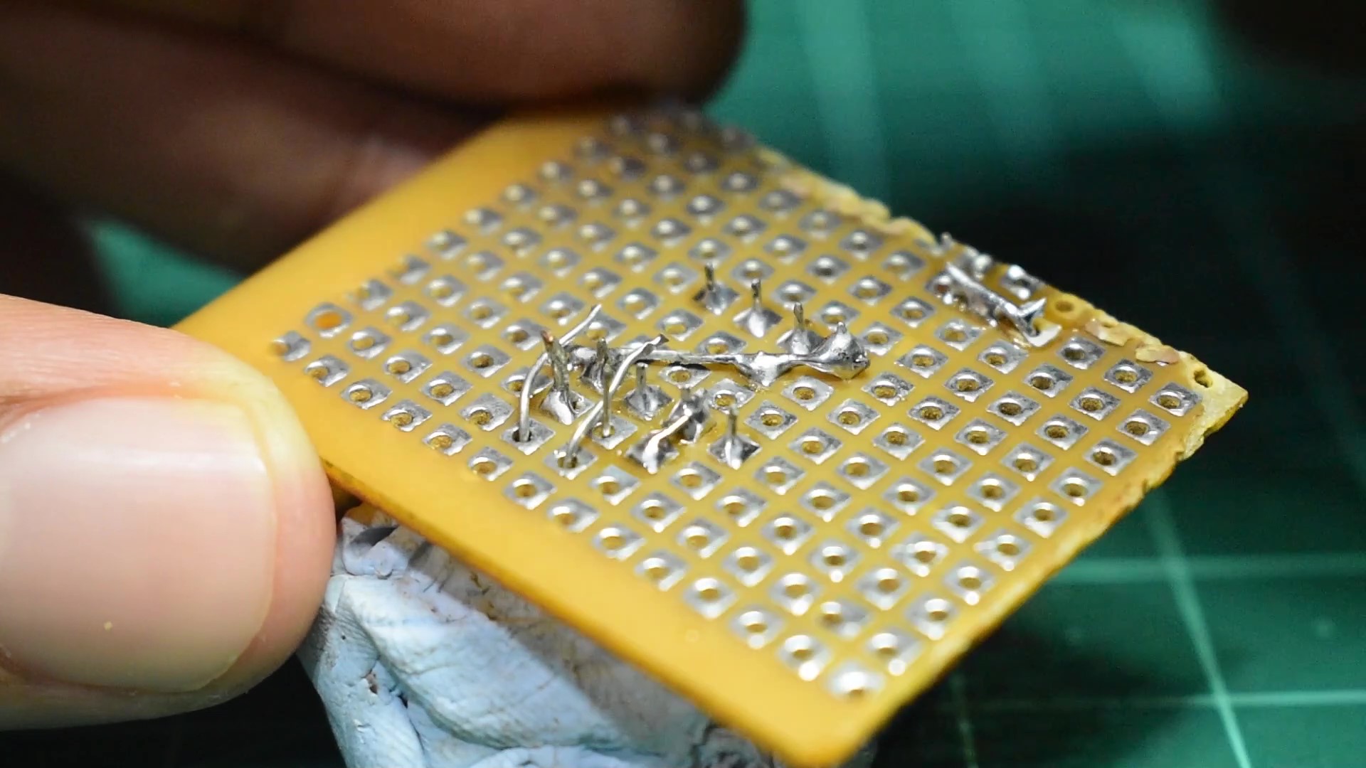
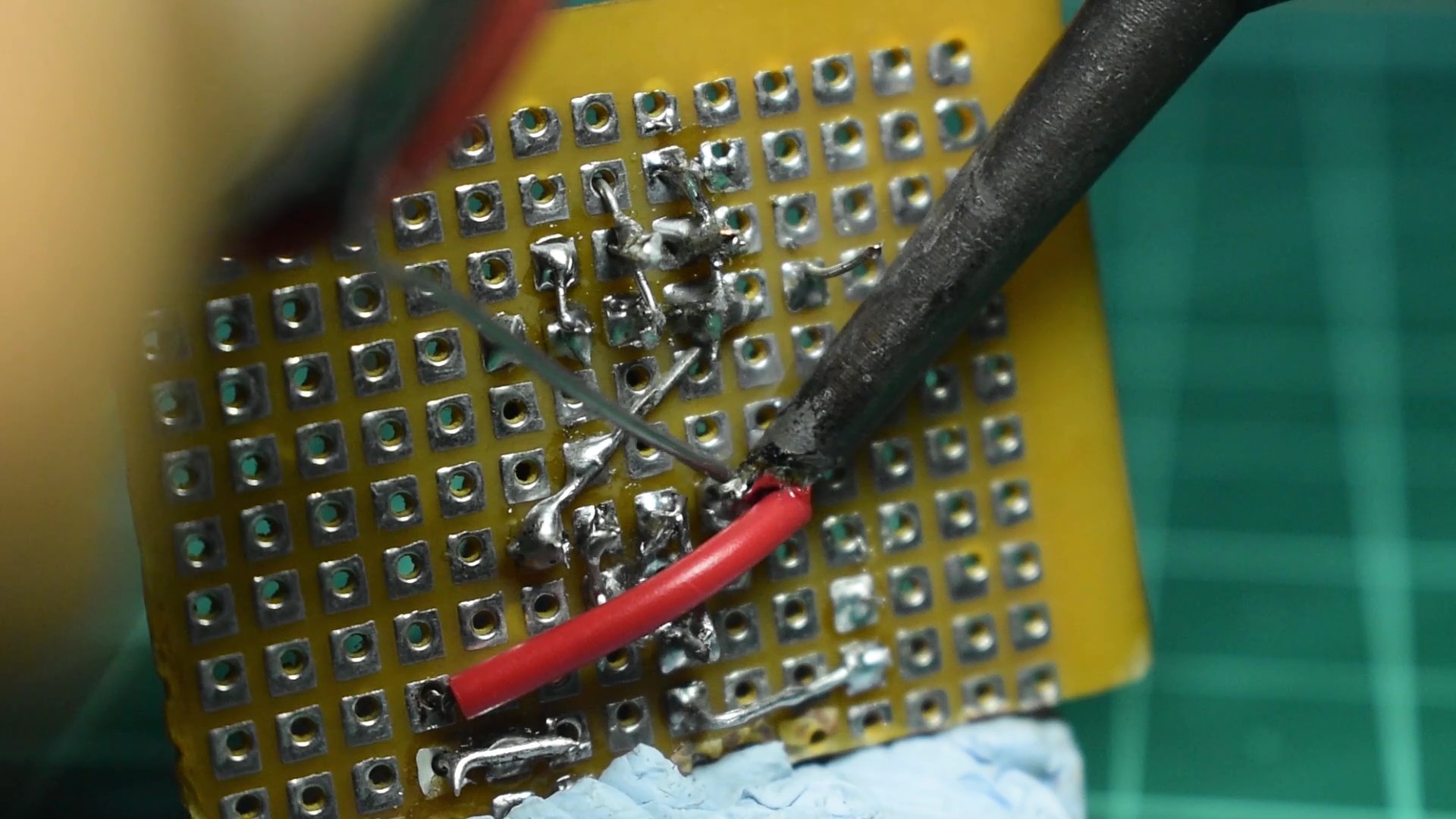
Once your Soldering iron is nice and hot, apply a little solder to the tip of your iron for better heat transfer,then solder the pins one by one making sure that each pin is separate and that there is no solder connecting adjacent pins.
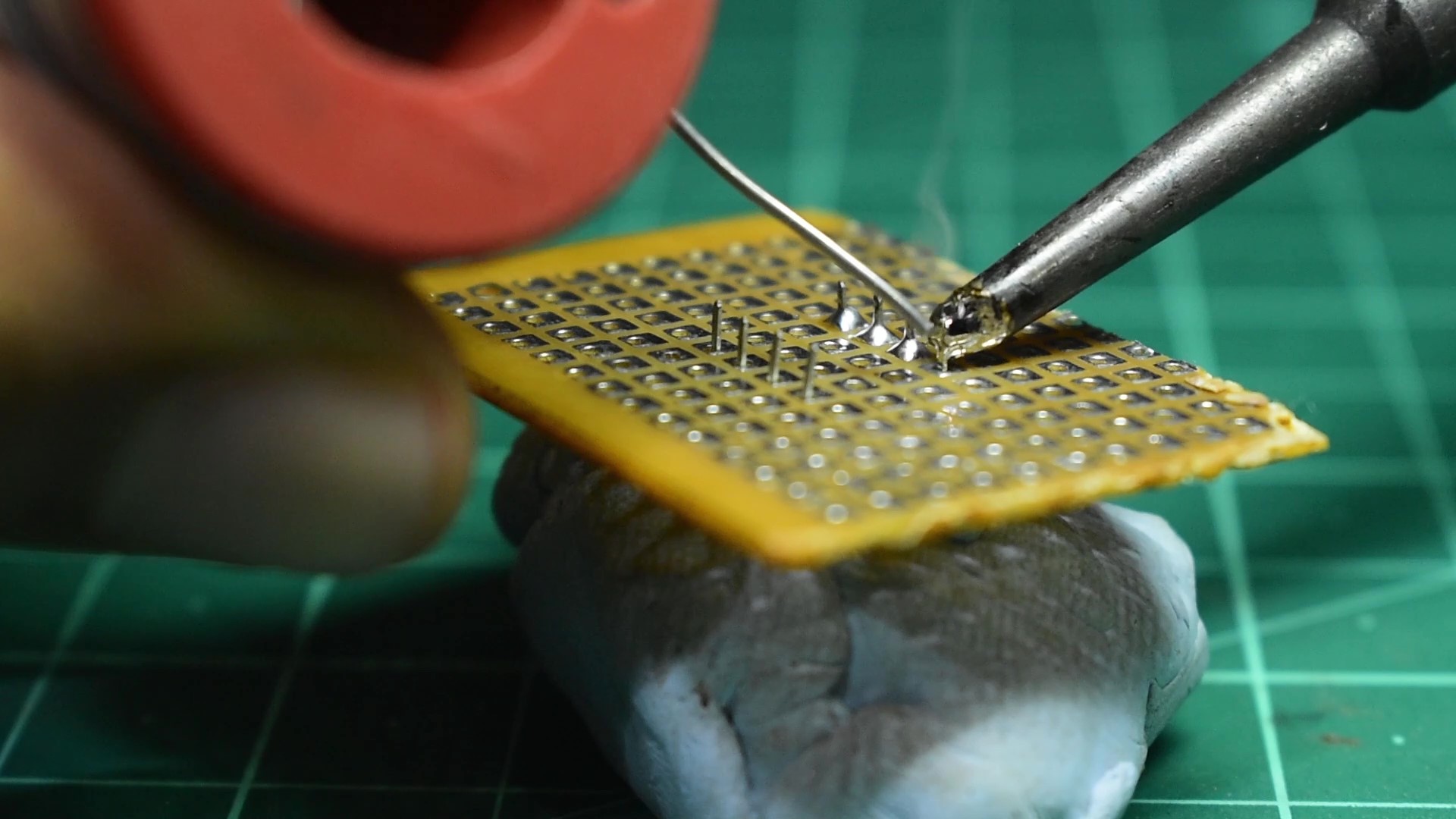

Before we move on to the next component,we need to do a connection between the IC pins,So we're going to connect pin no:s 4 and 8, to do that we're going to use the terminals on one of the LEDs, mark the required length and cut it, then hold the metal in place by just sticking a tiny amount of blue-tack.
Get your soldering iron and solder on the middle of the terminal to one of the Pads, so that the pin is stuck to the board and you can solder the edges of the metal rod at both ends to pin no: 4 and 8. Try to avoid getting solder on pads beyond the pins,because we're going to utilize the pads and we don't want any shorting. Now lets move on to the next component.
Component 2: Diode
The next component is the diode and we have to insert the cathode (White strip on diode) to pin no 8 ,while the anode goes to the positive supply of the input, in this particular design, towards your left is the output and towards your right is your input.
After soldering on the diode to pin no:8, trim of the excess leads.
Component 3: Resistors
Lets now install the resistors.First we're gonna install resistor R1 to pads parallel to pin no:s 7 & 8 and install resistor R2 to pin no:s 6 & 7.
So after installing the pins we're gonna cut the pins up to required length, such that they have length to connect through the diode and towards the IC pins,then solder the leads for both R1 and R2.
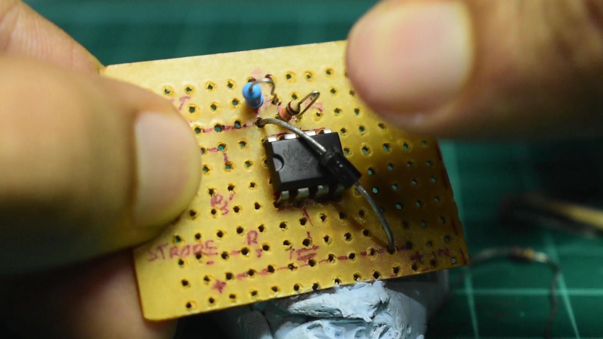
Next insert identical resistors R3&R3', in which R3 resistor goes to pin no: 3 and to the negative of the strobe LED, while resistor R3' goes to pin no:1 and the negative of the constant LED, on the Left of the PCB.
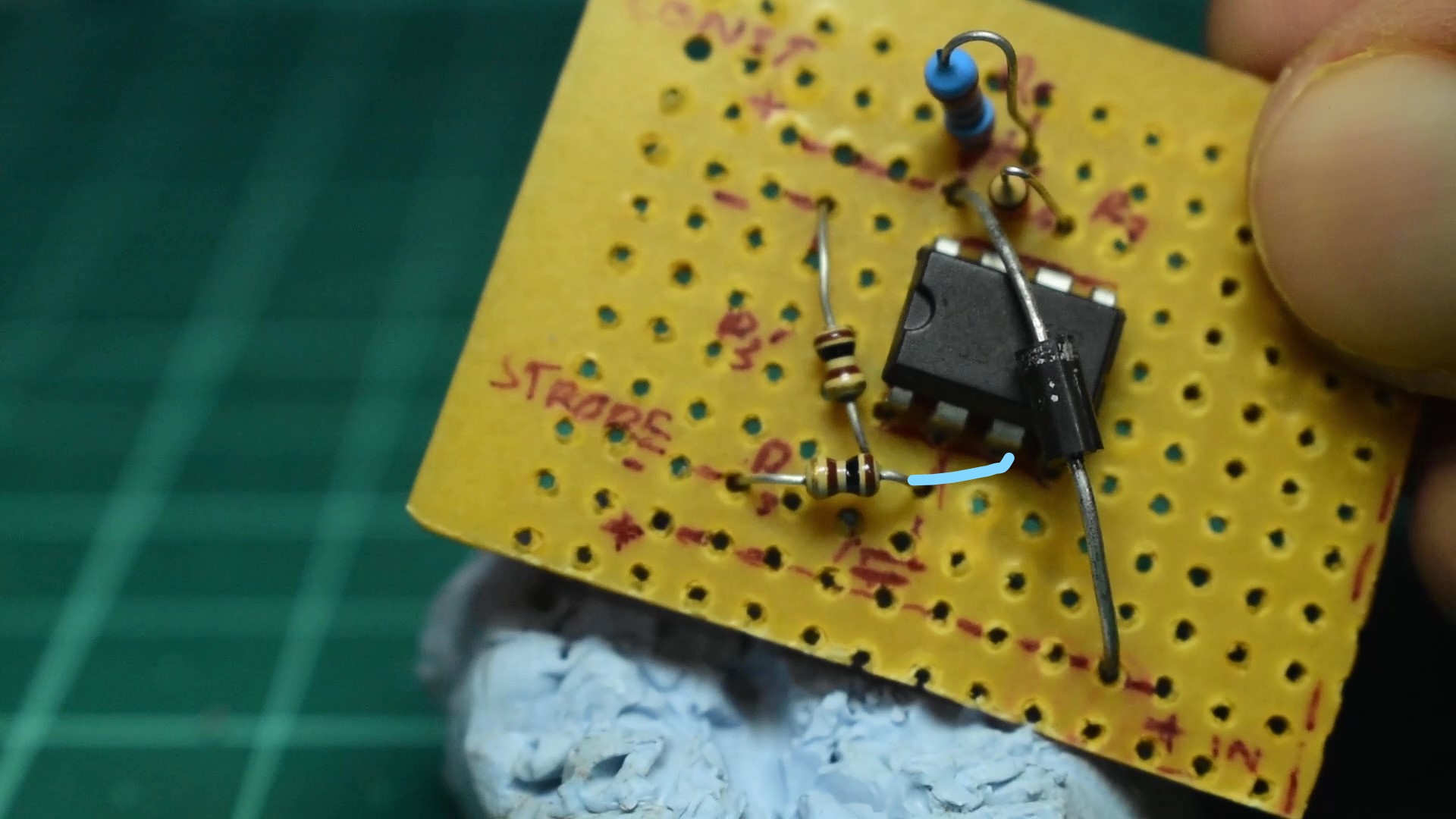
After inserting both the resistors to the required pins ,the next step is to solder them to the board cutting the excess off for the ends which go to the LED outputs while the end which goes to the IC pins must be cut to appropriate length ,bend towards the IC pins and solder on cleanly. With the resistors done,lets move on to the next component.
Component 4: Capacitor[10uf]
Lets now insert the 10uf capacitor in such a way that the positive terminal of the capacitor goes to pin no 2 while the negative terminal goes to the positive input of the PCB.

Once inserted into the desired pins apply a small amount of solder to both the terminals ,cut the terminals up to appropriate lengths and bend the positive to toward the IC also bend the negative terminal to the positive supply and create an extended connection.
Connections between IC pins
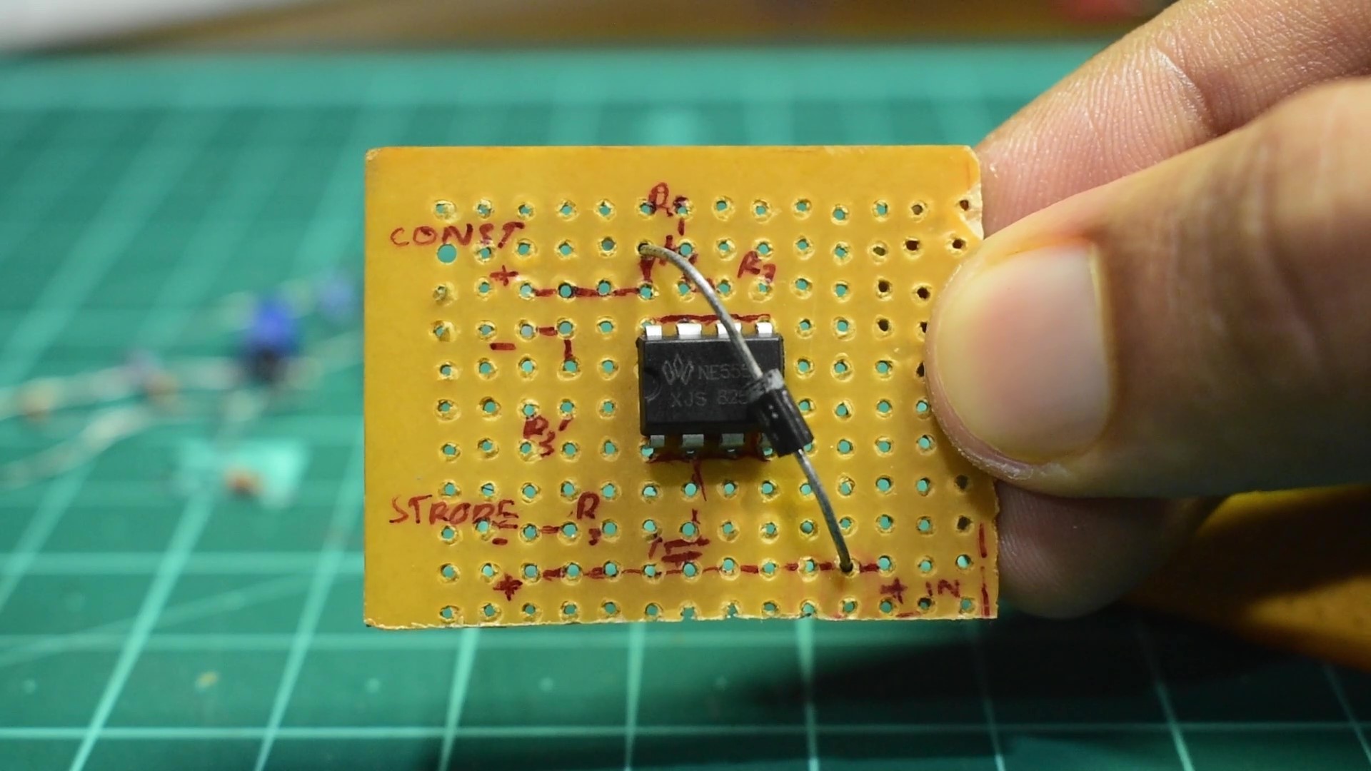
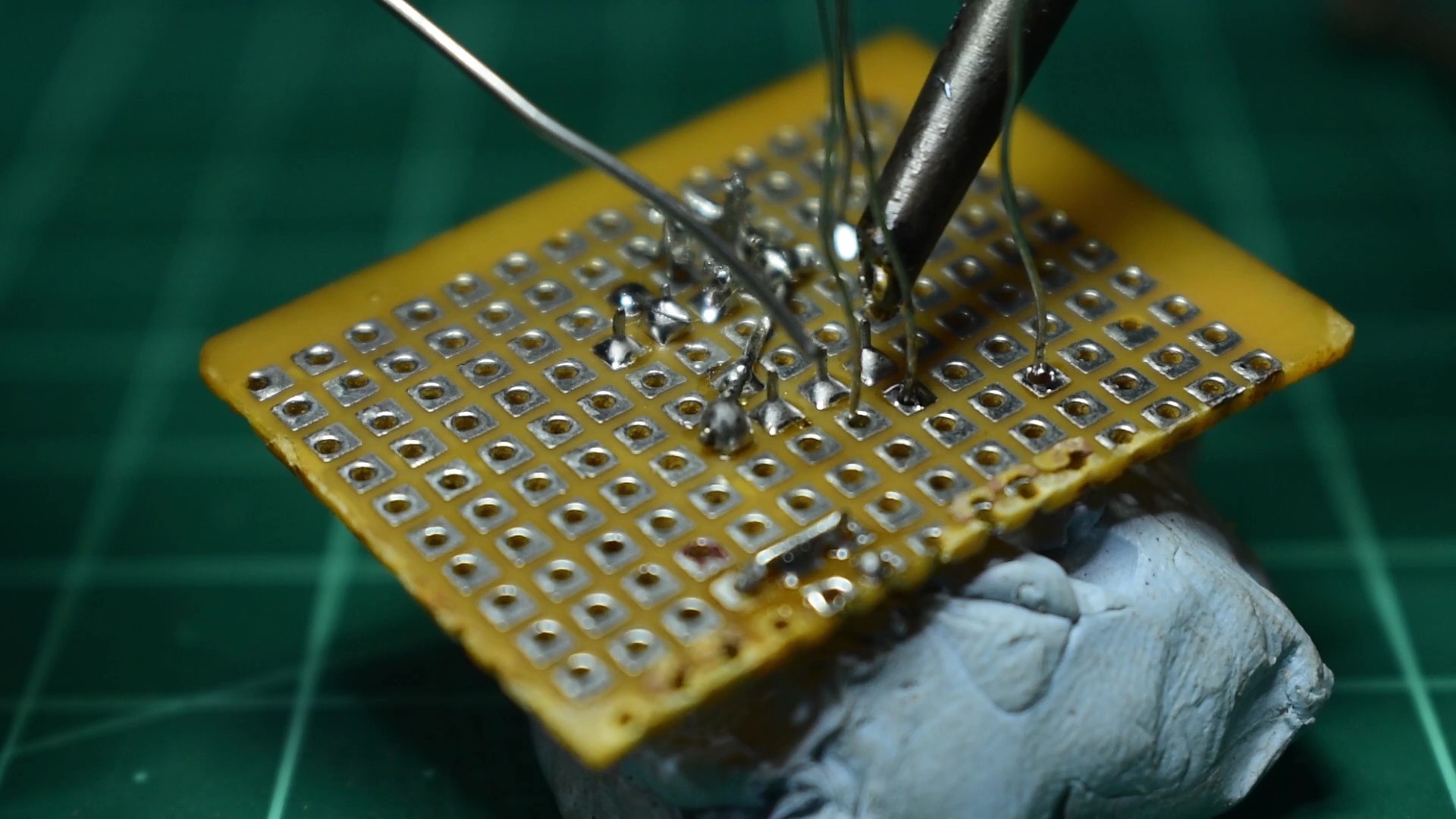
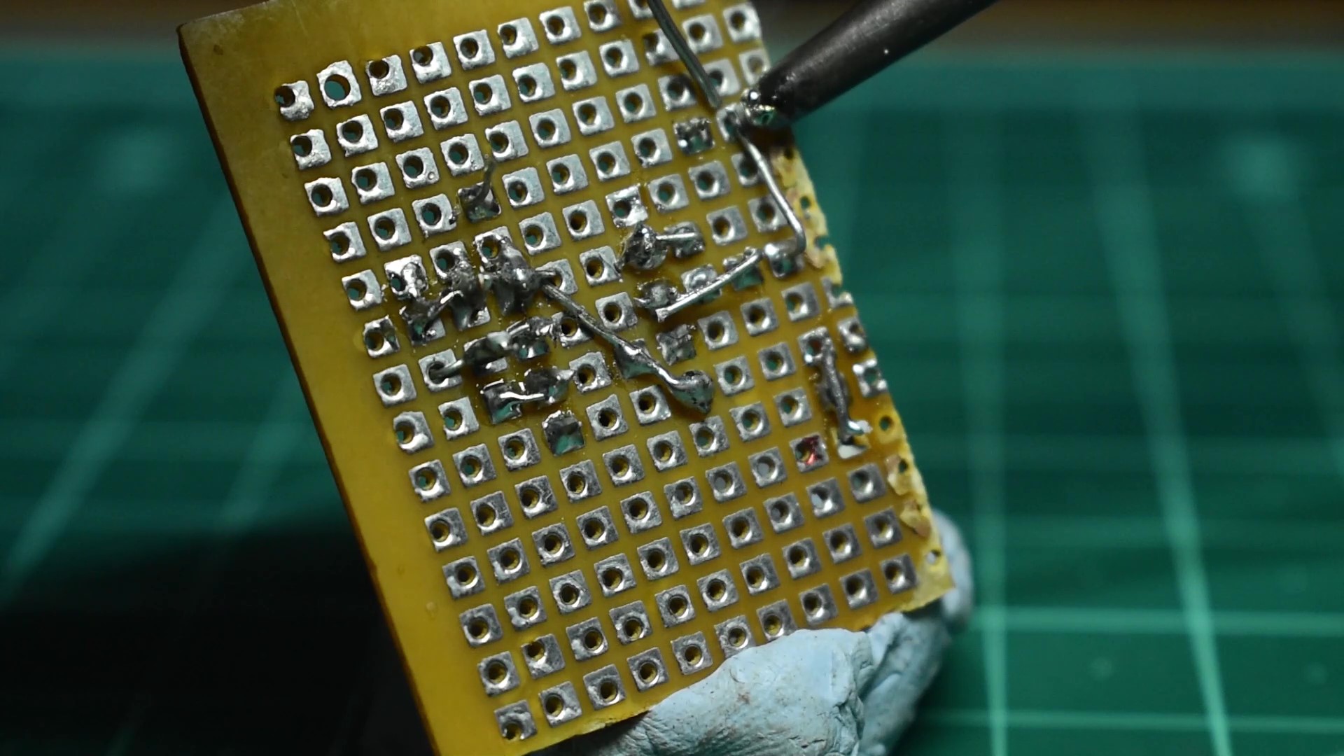
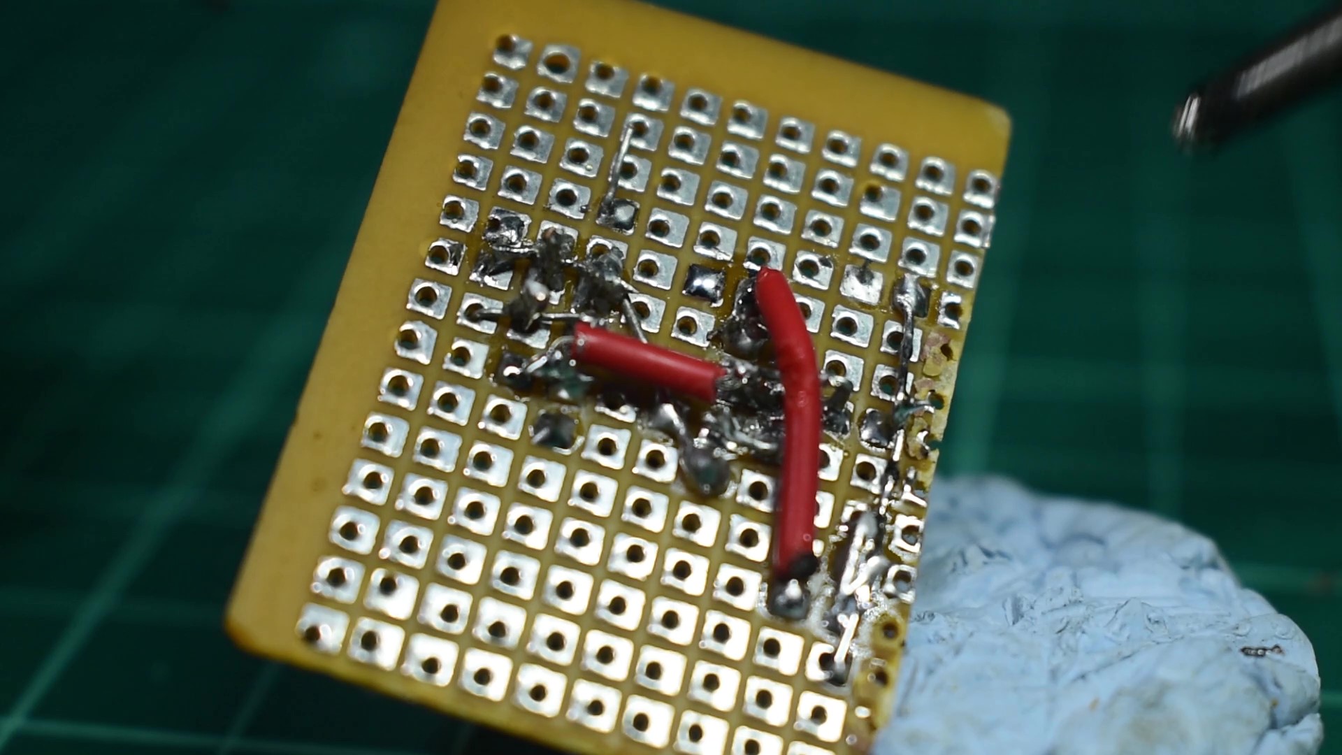
Now since all the main components have been successfully soldered on ,we have some important connections between the IC pins Which require the use of wire of small lengths .
a) Use a wire of appropriate length to solder a connection between Pin no:s 2&6 on the IC.
b)Similarly take some more wire to connect ground on the IC pin to the negative of the input on your right and solder them on securely.
With this our module build is nearly done ,but before we proceed any further lets test if the circuit works,you can do this by just plugging your LEDs and supplying power temporarily, again I'm using blue tack, if everything works that is, the strobe LED blinks and the constant LED turns on then lets proceed further .
Input Output connectivity:
There are many way to connect your module from receiver to module and from module to LED. One of the best ways to connect everything together is to either use pins similar to what you see on your receiver and solder them on to your PCB ,or you can use the ends of jumper cables to create custom connectors for both input and output. If you don't have any pins or jumper cables lying around, then your other only option is to solder the LEDs directly to your module.

I opted to create my own connectors from jumper-cables and it worked perfectly,
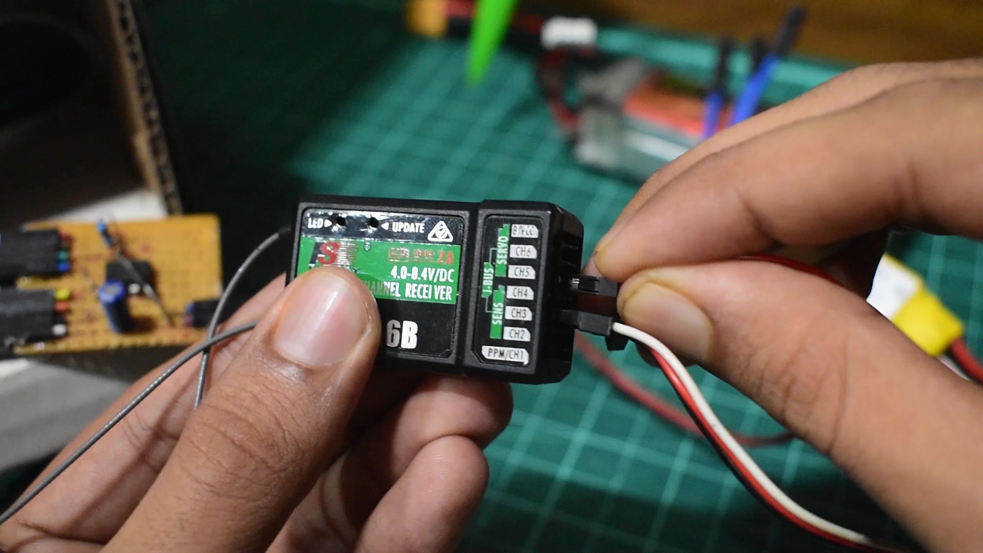
Final Testing on the airplane
Once you finish soldering on the connectors to the module, now is the time to test it with a receiver, Connect the positive wire from the module to the positive of receiver of any available channel like channel 5, and the negative to the negative or signal of the receiver, both work. Once you connected your module to your receiver then connect the battery and it should work perfectly, otherwise you might have to troubleshoot.

Conclusion
So that's how you make your own nav light system for your rc airplane.

This module design isn't perfect, it does have its flaws like, not all the constant LEDs work in conjunction when we use different color LEDs ,I think this is because the supply voltage to the LEDs are the same voltage ,as colored LEDs operate at different voltages, and also it cannot imitate the second red strobe on the top and bottom of the aircraft because this strobe flashes when the white wingtip and rear strobes turn off , achieving the timing required between the two different strobe lights with a single IC is difficult ,but if possible i'll design and make an improved version which rectifies all the flaws of the current module.
Thank you for reading my write up ,Hope this was helpful


Log In to reply
You just motivated me to make my own website!!
I've uploaded it on my Instagram page. because I don't have a website yet.
If you have any queries you can contact me through Instagram directly ,and I will help you.
Log In to reply