
In 2015, I took an excursion, of sorts, along the path of building bigger planes. I was inspired by Flite Test’s 400th episode featuring Monster Cruiser and Spitfire. My first attempt at enlarging a plane was the creation of the Supersized FT-22 at 150% bigger than the original Flite Test FT-22. After Upgrading the Supersized FT-22, it flew great and is one of my eye catchers at the field! Shortly after successfully completing that project, I turned toward one of my favorite fighter jets, the F/A-18E Super Hornet. Years previous to discovering FliteTest, I had already built a big one following the plans from Dave Powers using fan fold foam that seemed really heavy for its size, or so I thought. I wanted more - a lighter plane the would rocket around. So I set out to design my own. The result was the F/A-18 Super Hornet “FT-Style”.

This little guy has a 66 cm wingspan plane is really easy to build using techniques common to Flite Test builder and operates on only 3 channels. It really rocks with a small D2826 2200 kv motor! Several FT enthusiasts have build this model (Forum Thread)
Airfoil Wings
I had an itch to make it bigger. The Supersized FT-22 was made by simply enlarging the FT-22 plans and making slight modifications to account for the foam thickness not scaling with the rest of the model. The wings were flat wing panels that were skinned with fiberglass so that they could tolerate the stresses of flight without additional sparring. I wanted to build this Supersized F/A-18E Super Hornet with techniques accessible to Flite Test builders, i.e. no carbon spars or fiberglass wing panels. I seriously doubted that a 40 inch flat panel foam core wing would survive the stresses of flight, so I decided to build the wings with an airfoil shape.
Engine Nacelles
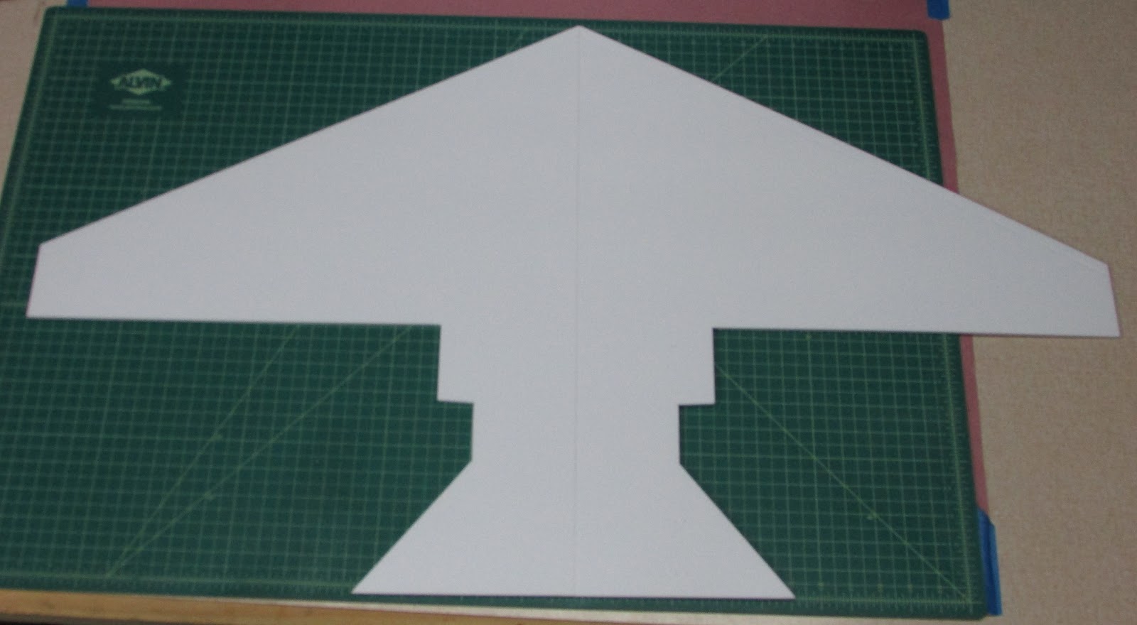
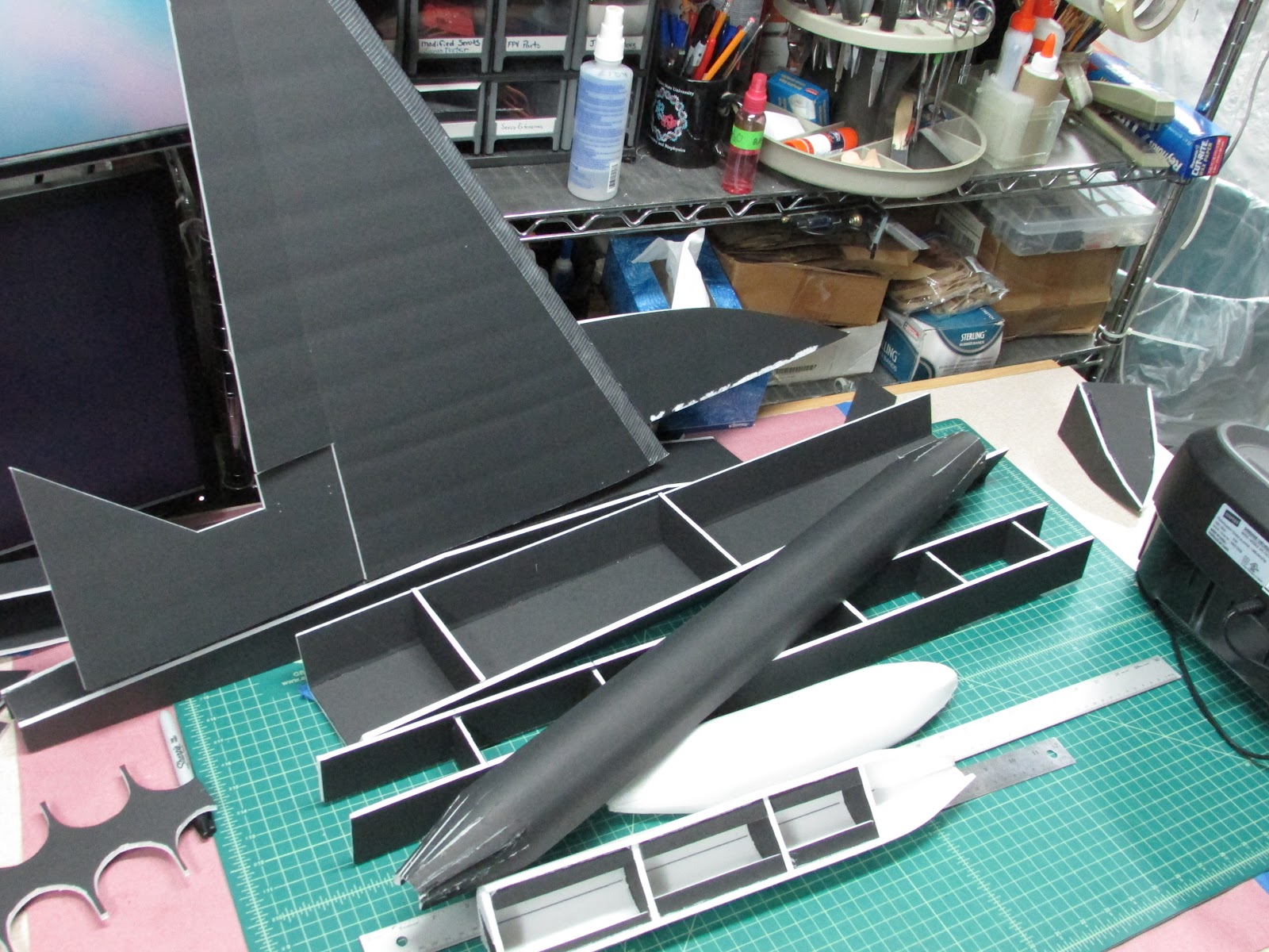
In addition to the airfoil wings, decided that the Supersized F/A-18E should have separated engine nacelles instead of a flat panel skid plate. I had my work cut out for me. This would be a little more complex than just enlarging the FT-18 plans. So, I grabbed profile pictures from the internet, dropped them into Adobe Illustrator and traced out the outlines of the parts. The size of the plane was determined by enlarging the plans until one wing was the same width of a foam core board 20 inches (50 cm). The wingspan would be close to 100 cm. With this as the guiding dimension for the rest of the plane, the fuselage from nose cone to the motor turned out to be just about the length of the foam core board. Perfect! - 152% bigger.
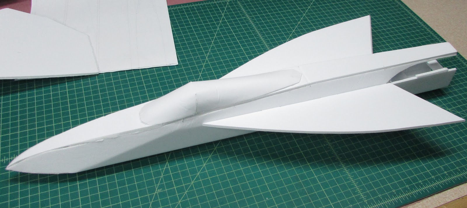
Rounded Fuselage
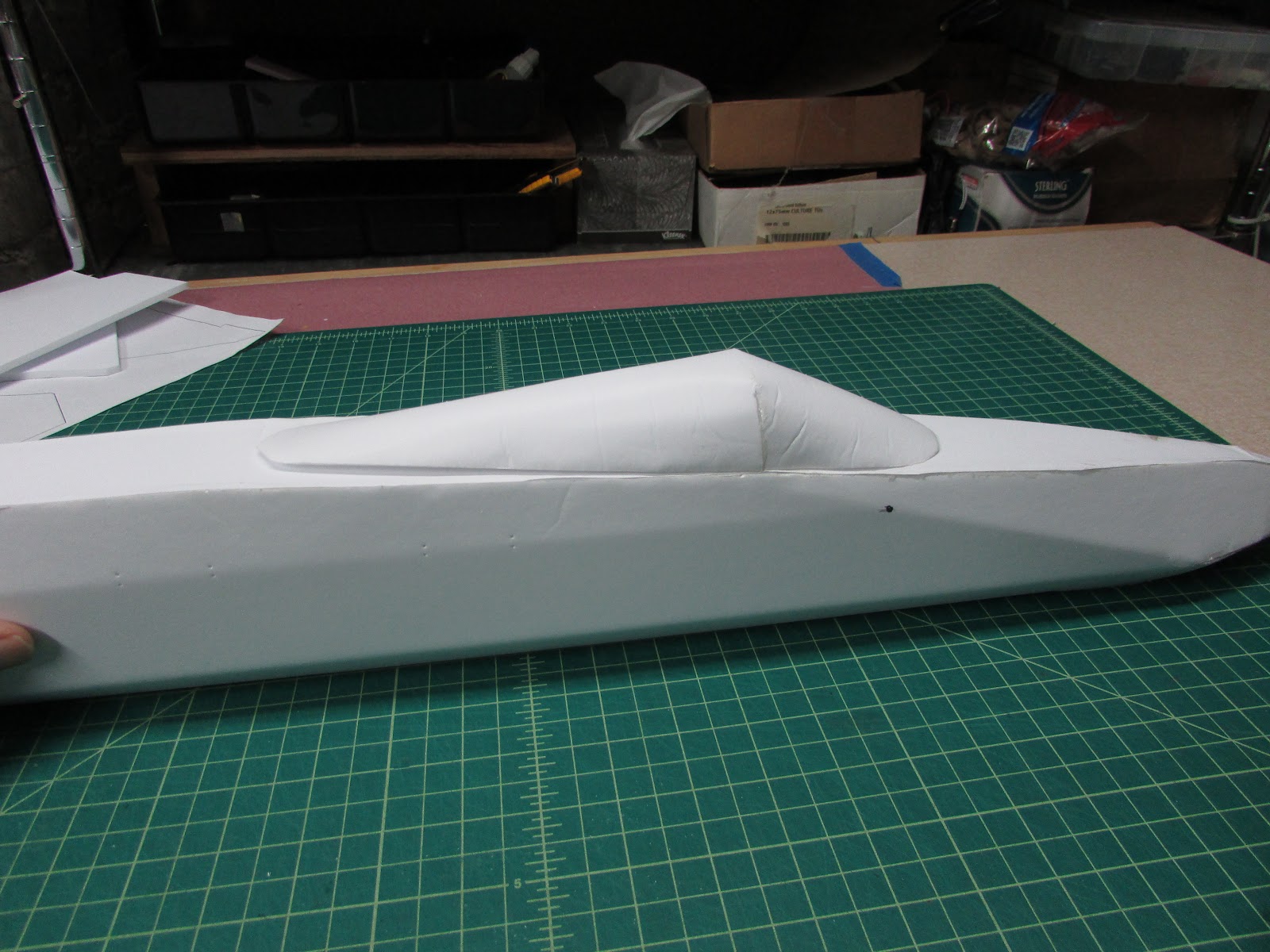
I wanted the fuselage to have a round look instead of the square box. Turns out it wasn’t as easy as I thought it would be… I made lots of attempts but it was just plain difficult and wasn’t turning out the way I wanted (See the appendix). I ended up making a the fuselage with a half octagon shape and I was quite happy with the results. I think this build is at an intermediate skill level, not simple like the small F-18, but definitely achievable by Flite Test builders.
Cutting out the plans
This plane will take at least 4 sheets of foam core, that is if you are really good at maximizing the foam usage as illustrated below. I can easily get the wings, vertical stabilizers and elevon control surfaces out of 2 sheets. The rest I cut out of 3 more sheets… it is just easier than trying to place the pieces onto 2 sheets and since it costs less than a buck… it doesn’t make sense to fret over the savings.

Everyone has their own favorite way of cutting out the plans. The FT Forum has a few really great threads dealing with the subject. Personally, I like to puncture a small hole at the corners of the pattern and then cut from dot-to-dot. The thing I really like about the hole poking method is that the plans stay intact and you don’t end up with a whole bunch of little pieces to keep track of.
Wings
Cut out the wing’s top and bottom panels. At this point, do not cut out the holes for the motor mount, propeller slot or tab holes for the fuselage, vertical stabilizer or nacelles… we’ll do that later. Note that the plans I produce include only one pattern for each part so when marking the second wing, invert the pattern face down so that the marks for the crease/bends will be on the inside of the wing. Mark the placement of the tab holes, motor mount, and propeller slot with puncture holes that go completely through the foam core.
Score cut the aileron hinge. Bevel the control surface. Bevel the leading edges of both the bottom and top wing panels.

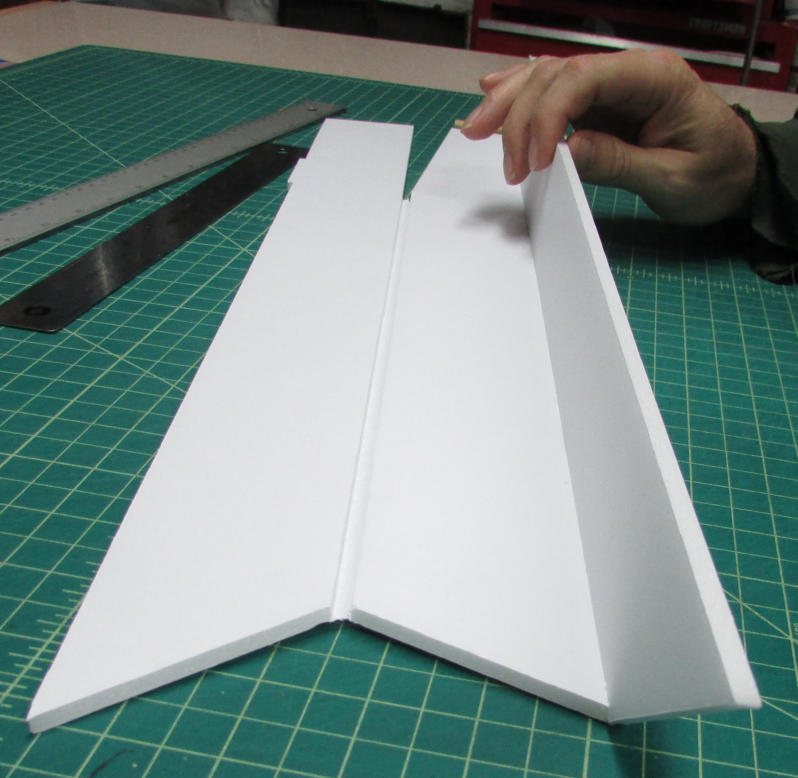
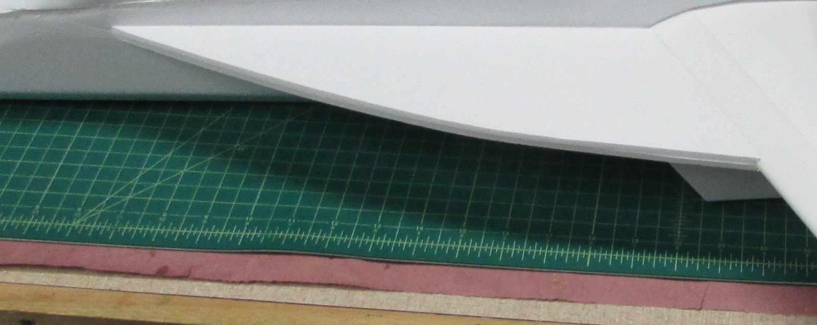
Crease along the fold lines using the round end of a popsicle stick. Use several light strokes rather than one heavy stroke.

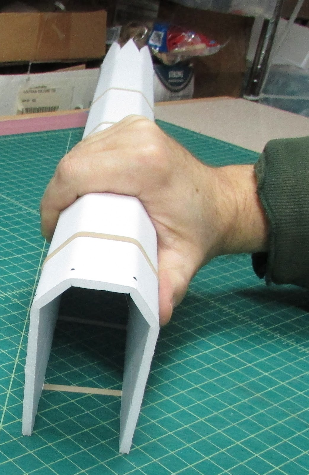
To finish the creases, I hold the crease line along the corner of my build table and press it into a curve using both hands (I’m holding the camera with my other hand). The creases/bends can also be formed by score cutting along the crease line, running a skewer along the score cut and secure the crease in place with hot glue while holding it in a bent position like most FT builds.
Attaching the Spar
The next step is to glue the wing spar to the top wing panel centering it between the last two creases. To make the spar, I don’t use the pattern - I can never get the two sides to be cut exactly even.
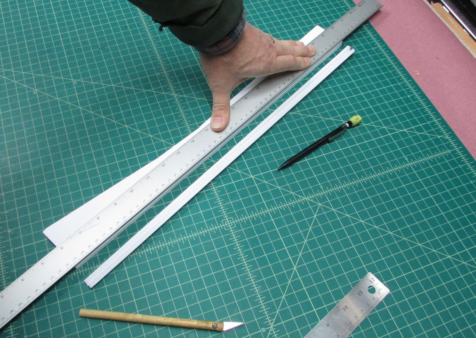
Rather, I score cut a 50 cm long piece of foam core and fold it onto itself and while folded two sheets thick, mark one end at 0.5 cm and the other end and 1 cm. Cut between the marks holding your knife perpendicular to the cutting surface and you’ll have a spar. Use several passes with the knife to get through both layers. The two layers are attached to each other with a paper hinge.

To complete the spar, run a bead of Gorilla Glue or Hot Glue down the paper hinge and

hold it against the build table to keep it straight. If you use Gorilla Glue, just use tape to hold the pieces together.

Attach the spar to the top wing panel centered between the last two creases/bends with masking tape. The tape should make a hinge to hold the spar in place.

The root of the spar should be sticking out off the wing’s root just a bit - it will be trimmed after gluing.

Roll the spar against the hinge to rotate the spar it off the wing panel.

Add hot glue and roll it back into position. You can also use Gorilla glue and use tape to hold the spar in place. Remove the tape.


Trim the spar so that it is flush with the wing root.
Joint the Top and Bottom Wing Panels
Joint the bottom wing panel to the top wing panel along the leading edge.

I run a piece of tape along the leading edge of the bottom wing panel. After securing the tape, turn it over.

Hold the top wing panel so the points at the root of the leading edges align. Press the top wing panel into the tape.
Slowly press the top wing panel into the bevel cut of the bottom wing panel and with your thumb press it into the tape. The leading edge of the top wing panel will slide down the bevel cut and get stuck in the tape. It should be a perfect fit.

Flip the wing over and lay the leading edge joint over the edge of your build table and finish pushing the tape onto the foam core.
If you used the score cut and hot glue technique to create the airfoil bends in the wing panels, with the spar attached and the wing panels attached to each other, now is the time that you will add hot glue to the score cuts and hold them in place. With the bottom wing panel laying flat on the table, run a bead of hot glue along all of the score cuts, fold the top wing panel over until the top panel rests on the spar and the trailing edges meet. Hold until the hot glue solidifies.
Joining the Two Wings.

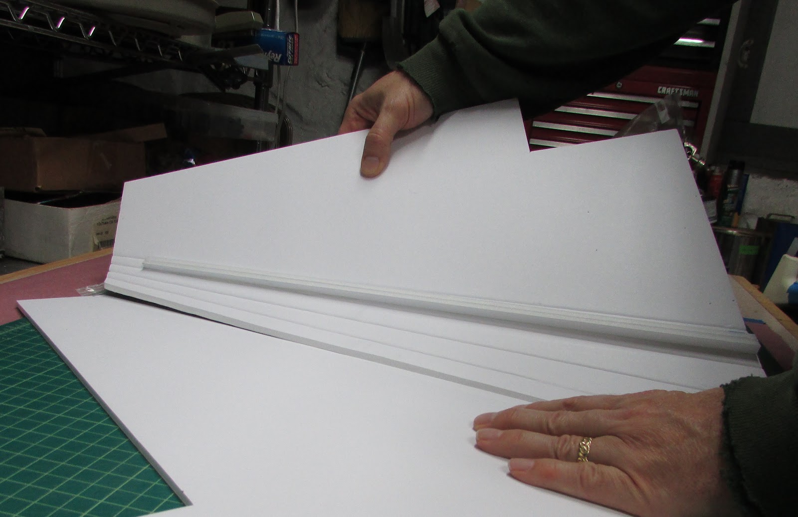
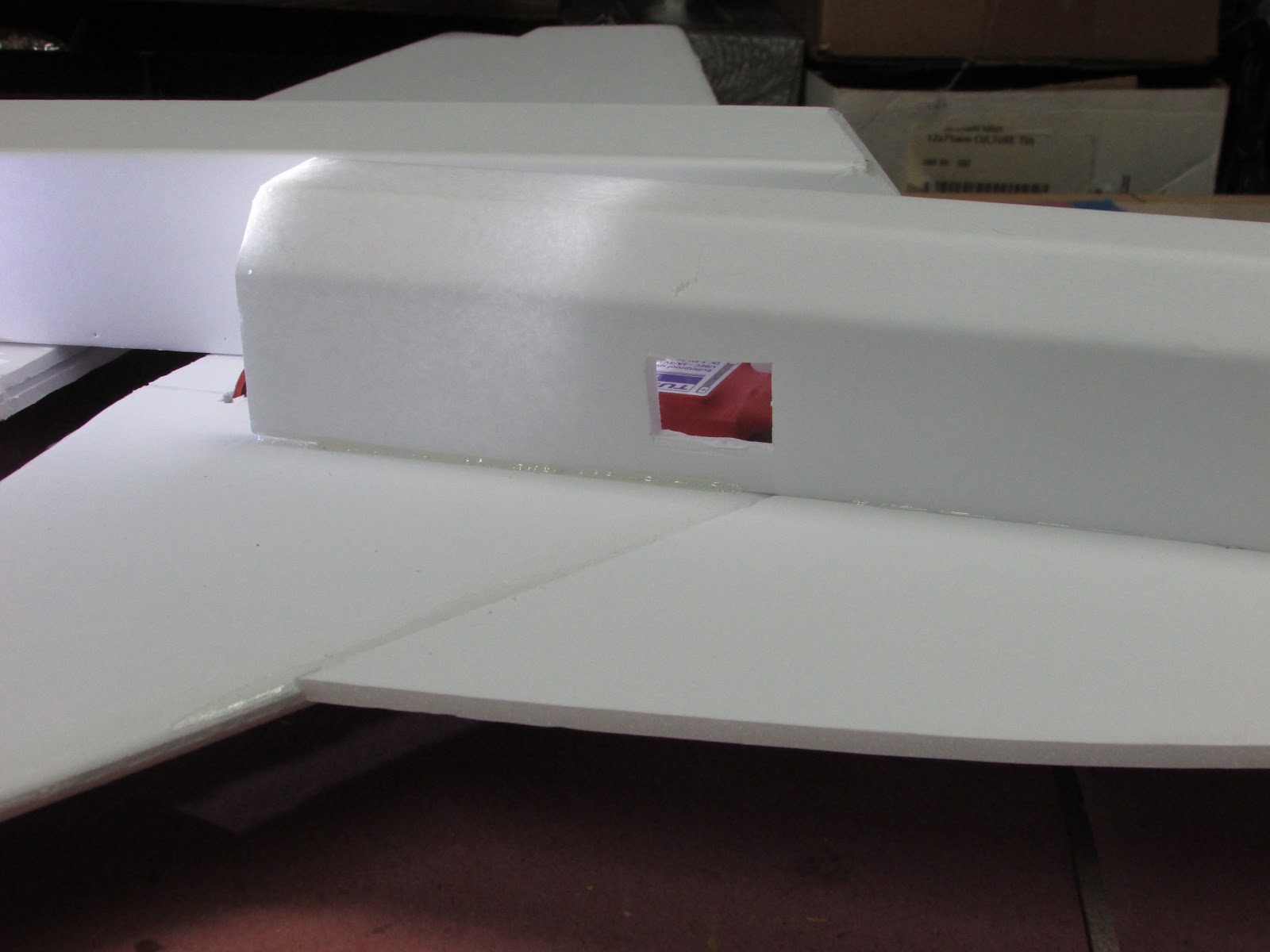
I like using Gorilla glue to join the wing panels together, but you can use hot glue if you want to. Use masking tape to hold the wing panels together making sure the edges of the tails are aligned.

Once taped together, open the tape joint by lifting the center of the panels off the table and add Gorilla glue to the length between the two bottom panels and lay flat. Add Gorilla glue along the leading edge bevel cuts and along the length of the spars and along the edge of the top wing panel (marked in red). If you use hot glue, the same steps are followed only don’t try to do it all at once. Just make sure that the center of each top wing panel does not cross the center seam of the bottom panels and that the top wing panel is pressed into the spar.
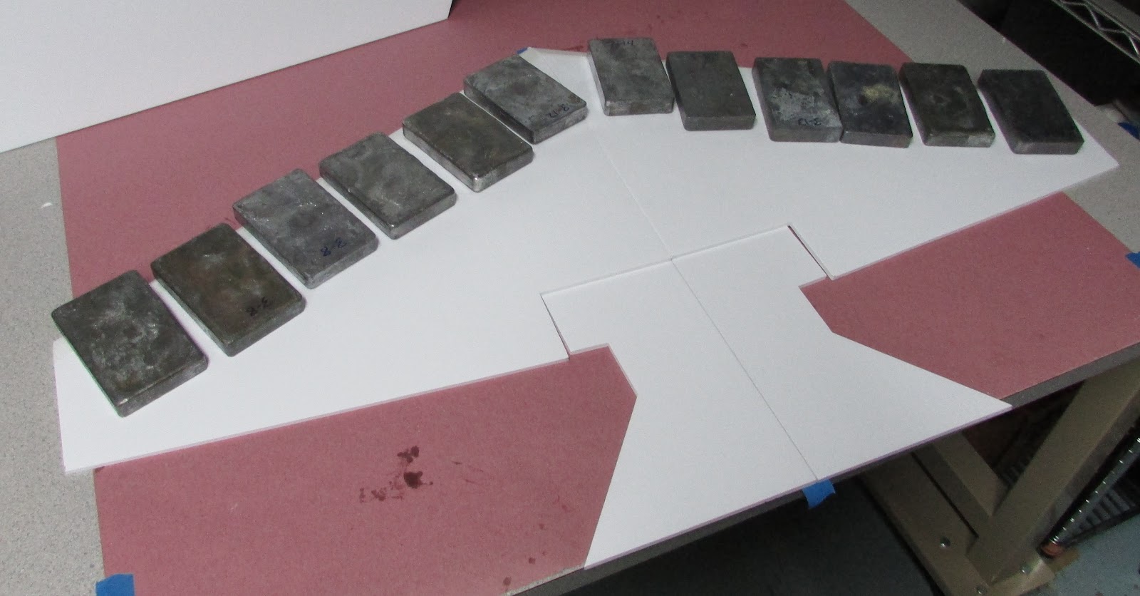
Roll the top wing panels over the bottom wing panel that is laying on a flat surface and hold in place until the glue cures. If you are using Gorilla glue, I suggest using weights placed along the spar because it takes a few hours to set. The excess Gorilla glue that oozes out of the crack can be easily cut off with a one-sided razor blade or sanded off. After curing, remove the masking tape and if you want, the tape used to form the leading edge. Some people like leaving it on for added strength.

Next, cut out the fuselage tab holes in the bottom of the wing panel.

While you are at it, you might as well cut the four tab holes for the engine nacelles.
Making the Fuselage

Cut out the outline of the fuselage. I like using pinholes to mark the places along the plan lines and then cutting from dot to dot. For the nose cone area, I draw a line from dot to dot and then just freehand the cut along the lines. At this point all the pinholes are on one side of the board. Since some of the pinholes mark the location of wing slots and tab holes that will be cut later, they need to be on the outside of the fuselage after it is formed. The only pin holes that need to be on the inside of the fuselage are those that mark the crease/bend lines.

There are six holes on the rear of the fuselage and

two holes near the nose cone that need to be punched through to the other side (marked in black above). After these pinholes are punched through, flip the foam core over so the side with all the pinholes is face down. Only the visible holes should be those marking the placement of the crease/bend lines.

Crease along the lines (between the pinholes) with a popsicle stick.

It’s hard getting a photo of the crease lines, but this is what it should look like.

Cut a bevel along the inside edges of the fuselage nose points that will form the nose cone.

Use the sharp edge of the build table to bend along the bottom four crease lines.

The bottom of the fuselage should bend into a “U” shape with the bottom being half of an octagon.
Bend the fuselage in the “U” shape and hold it with rubber bands. Add hot glue to the fuselage formers one at a time and put them in place by spreading the fuselage.
While the glue is cooling, ensure the top of the “U” is flat by holding the fuselage upside down against the build table surface.

The formers should be placed every 8 cm starting from the rear of the fuselage.

The rear most former, a rectangle piece of foam, is added last and glued between the side cheeks of the fuselage anywhere from the octagon bend to halfway up the side cheeks. Any higher may block the wing from sliding into its slot. You’ll see how this all works a bit later.
Gluing the nose cone.
Before gluing the nose cone points,

bend the nose cone side cheek panels. These are the creases that run from the first “V” to the canopy as marked above in blue.

Crease and bend all the points so they arc towards each other.

Glue the two side cheek points together.

Then glue the points just below the side cheeks to the side cheek points on both sides. This takes a bit of pushing up on the lower point. Just hold it until the glue cools.

When both sides are glued, the bottom most point is glued to both sides.

The bottom part of the nose cone is complete.
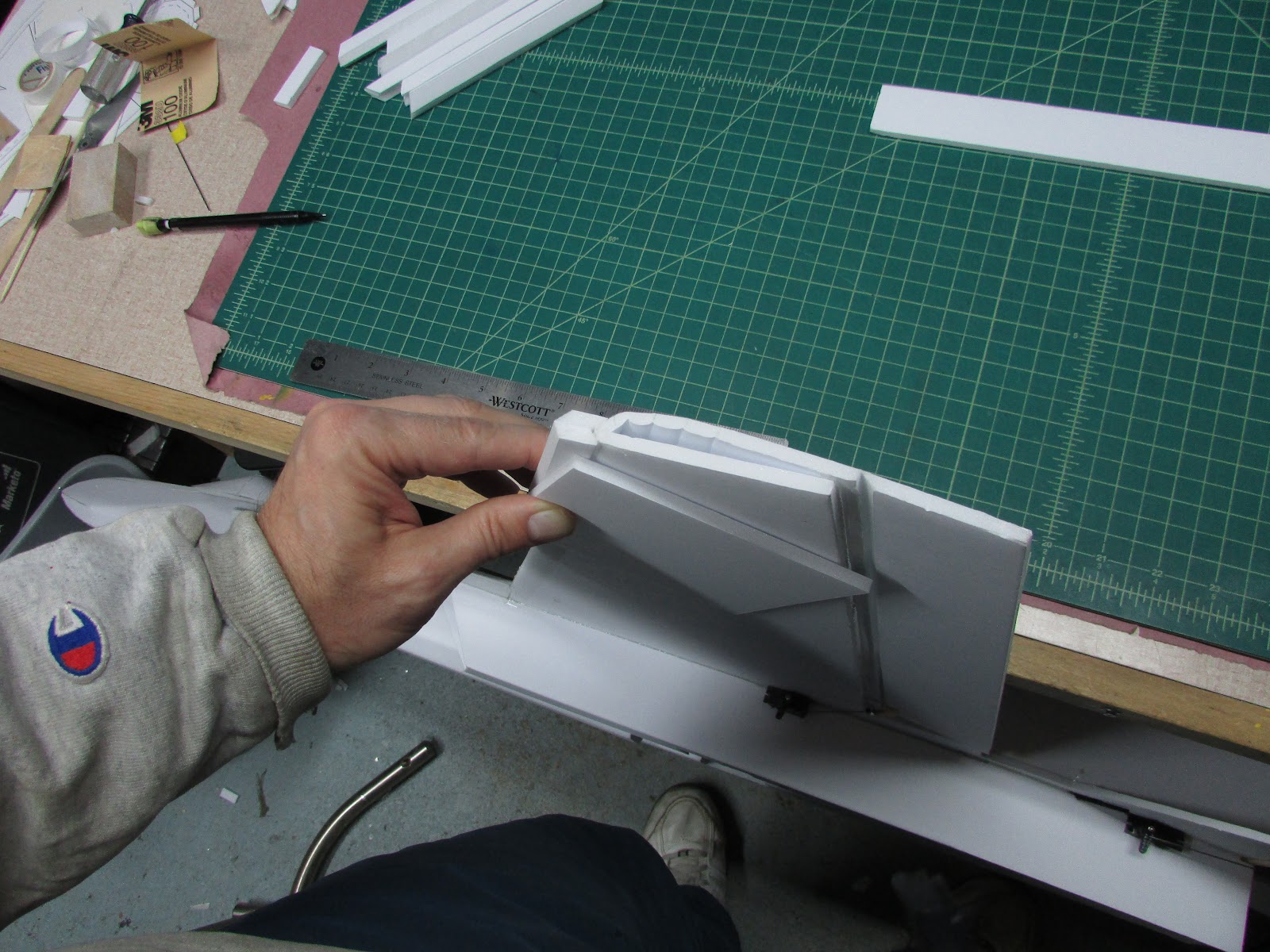
Battery Tray Platform
The next step is to add the battery tray platform to the top of the fuselage formers. Since the battery is used to adjust the balance of the plane to the CG, I like keeping my options open as to where the battery is placed until the end. After the fuselage is formed, the battery tray is glued to the battery tray platform.

The platform is a flat 5cm by 25 cm piece of foam core (bottom) that is glued from the front point of the wing (marked by pencil below).


The battery tray will be added after the model is complete, but it is made by folding the piece back onto itself along the lines marked on the plan and adding velcro to hold the battery. The battery tray is positioned along the platform to balance the aircraft. It can be shortened to the length of your battery.
Here is a picture of the battery tray platform with the battery tray moved forward. For this build the balance point was achieved by gluing the battery tray to the battery tray platform 8 cm forward of the wing leading edge point. You should finish the build and then glue the battery tray to the battery tray platform at the location to balance your plane.

Next, cut out the wing slots. With your hands, bend along the top most crease/bend line that extends from the wing cutout to underneath the canopy location so the the fuselage top piece fits. When it fits together comfortably, it is ready to be glued.

Glue the fuselage top panel to the fuselage starting at the rear. Add hot glue to the top edges of the fuselage “U” from the rear to the marks for the battery hatch cover (which is the marked above). Do not glue along the length of the battery hatch cover (from the front of the wing to the battery hatch hinge).

Continue to work your way forward by gluing the fuselage top panel to the fuselage from the battery hatch hinge to underneath the location of the canopy. The last step is to glue from underneath the canopy to the nose. To get glue between these pieces, I lift the fuselage top piece, add glue and then hold it in place.
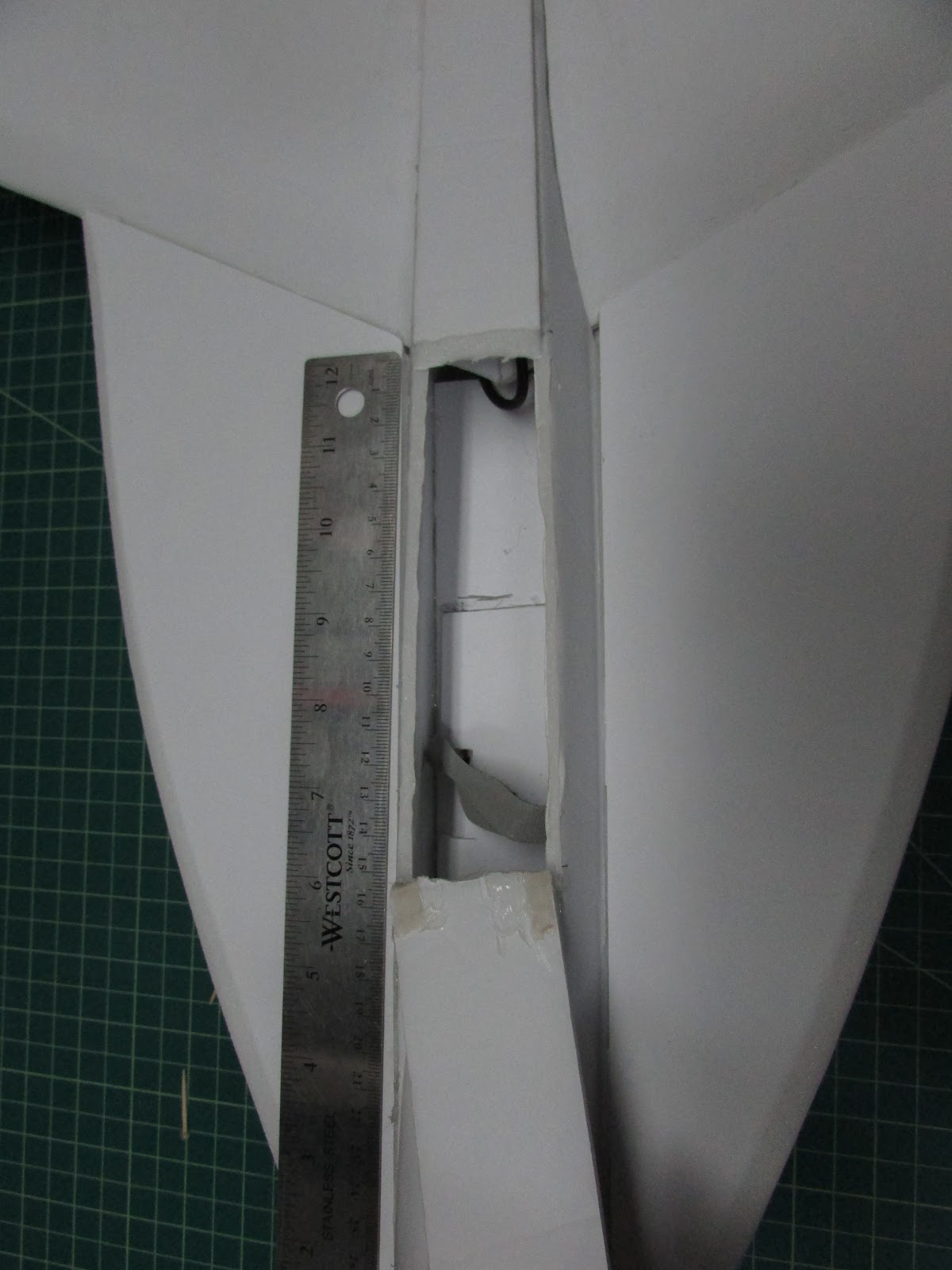
The last step is to make the battery hatch work. In the rear, I but it at an angle to to make a jam. The hatch is held shut by gluing a couple of pieces of scrap foam to the underside of the hatch and then poking a toothpick through the side cheeks.
Building the Canopy

Cut out the canopy piece and peel the paper off of one side which will become the inside.

Gently bend the canopy and massage it into a nice curvy shape.

Add glue to the notch and push it together. Hold it until the glue completely cools.

At this point the canopy has a general shape, but it is really hard to hold the curve while gluing it to the fuselage. To help me I use some rough formers. Cut four pieces of scrap foam with the lengths of 4, 4.2, 3.7 and 3.0 cm long.
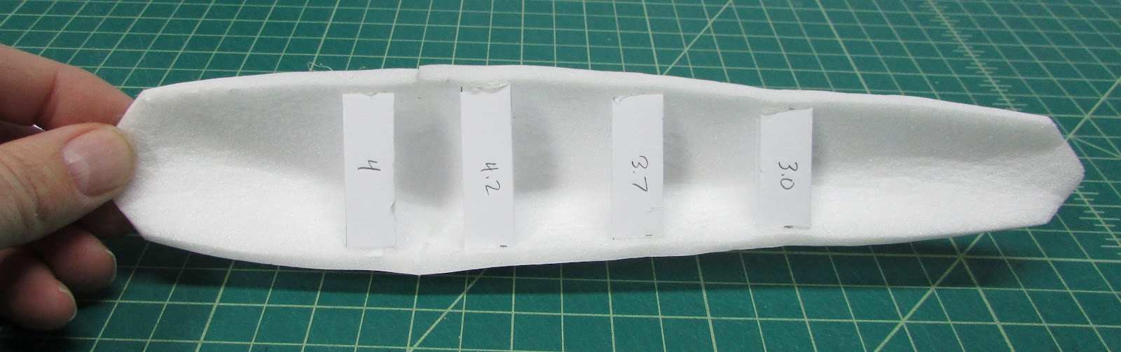
Glue the pieces of foam into the canopy as shown above to hold it in the curved shape.

The bottom edge of the canopy needs to be flat. Lay a piece of sandpaper on the edge of the build table and sand the front and rear points. The canopy can be glued to the fuselage now or later.
The position of the canopy is placed on the fuselage so that rear point meets the battery hinge as shown above.
Leading edge extensions

Cut out and bevel the rear of the leading edge extensions, the edge that will mesh with the wing. There should be four of these, the two bottom panels will have tabs and two top panels should not have tabs.

The bottom panels with the tabs should be beveledup and the top panels beveled down so that when they are glued face to face they form a “V” for engaging the leading edge of the wing. Put them aside for a few minutes.
Building Nacelles
Build the nacelles by cutting them out and gluing them together using a “B” fold

The restriction portion to the rear can be glued together.

Test fit them to the underside of the wing (do not glue at this point, just make sure they fit).

Cut out the motor and propeller holes that are marked on the top wing panel. Using a poking tool, mark the edges of the propeller slot through the bottom wing panel and cut it out.

Glue in the motor mount. In this design the motor mount was an FT- Elements plan that I cut out of ⅛ inch plywood on the sides and bottom and ¼ inch plywood for the motor side. The front of the motor mount slides under the wing panel and abuts the spar.

The motor wires feed through the bottom wing panel. I glue the ESC to the front of the bottom wing panel between the two fuselage tab holes as shown.

When the wing is slid into the fuselage the ESC will slide by the rear fuselage former.
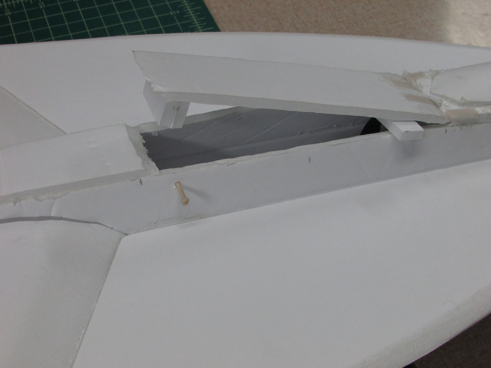
Cut the ESC Cooling holes in both sides of the fuselage. With all the pieces in place, it should test fit as above. The nacelles cover the cooling holes pretty nicely. One advantage to this design of having all electronics attached to the wing (that I haven’t tested yet) is that after a bad nose crash, the fuselage can be cut off and a new one installed without touching the wings or electronics. - bonus! An alternative design that I did not pursue would be to mount the motor on a flat plate glued to the rear of the fuselage. This design would be more sleek since it would not have the motor mount sticking up through the top of the wing. Maybe I’ll try it next time.

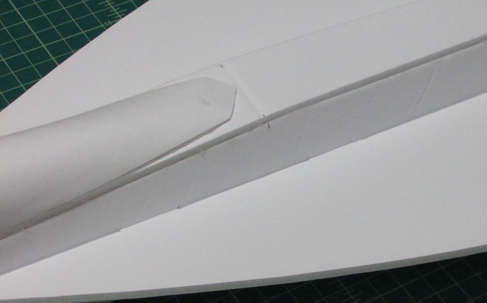
With the fuselage wing tabs engaged in the wing, the bottom leading edge extensions should fit into their tab holes in the fuselage and meet the underside of the wing’s leading edge.
When all the pieces fit properly, it’s time to start gluing it together.
Start by glueing the leading edge extensions to the fuselage. These become the guides to get the main wings on straight.
Glue the fuselage to the wing

Slide the wing into the wing slot and make sure the tabs on the bottom wing panel are fully engaged with the fuselage tabs. Make sure the wing is pushed all the way forward into the leading edge extensions and that the both leading edge extensions are flush with the wing’s leading edges. Without moving the alignment, hold the fuselage tight against the bottom of the wing and run bead of glue along the fuselage/wing joint on both sides. After it is cooled flip it over and glue the fuselage to the top of the wing.
Glue the leading edge extensions to the wing

Push the leading edge extensions down a bit and add hot glue to both the left and right sides. Lift both leading edge extensions making sure that they run smoothly along the underside of the wing.

The top leading edge extension can be glued. If you use Ross foam core, you can use a water based glue like Elmer’s. Hot glue will work, but I would suggest warming the panels with a hair dryer so the glue stays pliable longer. Since this is basically decoration, it can be glued with a single bead around the edges.
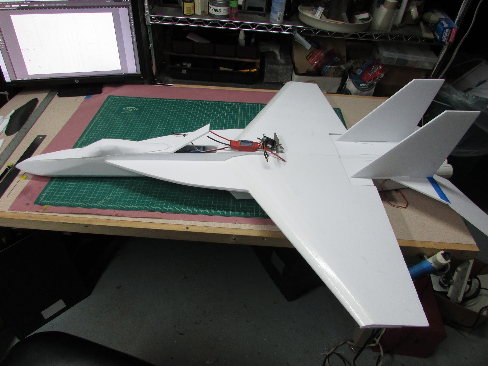
The end result should look like this.
Placement of the Electronics
Almost all of the electronics are hidden within the engine nacelles.

With the nacelle in place, mark the location and position of the servos and draw a line along the inside nacelle panel to help locate the receiver location. Also, mark the location of cutouts for the servo wires.

Lift the nacelles out of the way and glue the servos in place. I tac down the servo wires with hot glue and paper over the top to hold them in place. I use coffee stir straws to hold the receiver antenna in place. Cut notches in the nacelles at all of the locations where wires and antenna travers the nacelle/wing joint. When you’ve got everything in place, now is a great time to hook up a battery and make sure the motor spins the correct direction and the servos are centered. I will share with you a piece of advice that I learned the hard way. The wire running past the propeller needs to be kept out of the propeller. Running the ESC control wire across the propeller notch as you see it above is dangerous because it is so close to the propeller. It is just setting there. After I glue the nacelles in place I move the wire and attach it to the furthest corner of the nacelle away from the propeller. Make sure the wire crossing the propeller notch is well secured.
Glue the nacelles in place

Practice fitting the nacelles to the wing a couple of times. Run a bead of glue down the inside edge of the nacelle and hold it in place. To glue the outside edge, I lift it up a bit off the wing and run a bead of glue underneath it and then press it back into place. With the nacelles in glued in place, finish cutting out the propeller hole in the nacelles so that the propeller slot matches the wing. The plans are marked with the approximate placement but can be altered to fit your desires. My ESC control wire is glued in place to the far left corner of the nacelle to give it a few more cm distance from that wire cutting-propeller.
Attach the elevon control surfaces to the tail.

I secure the control surfaces to the plane with masking tape and use polyester cloth to make a “X” hinge.
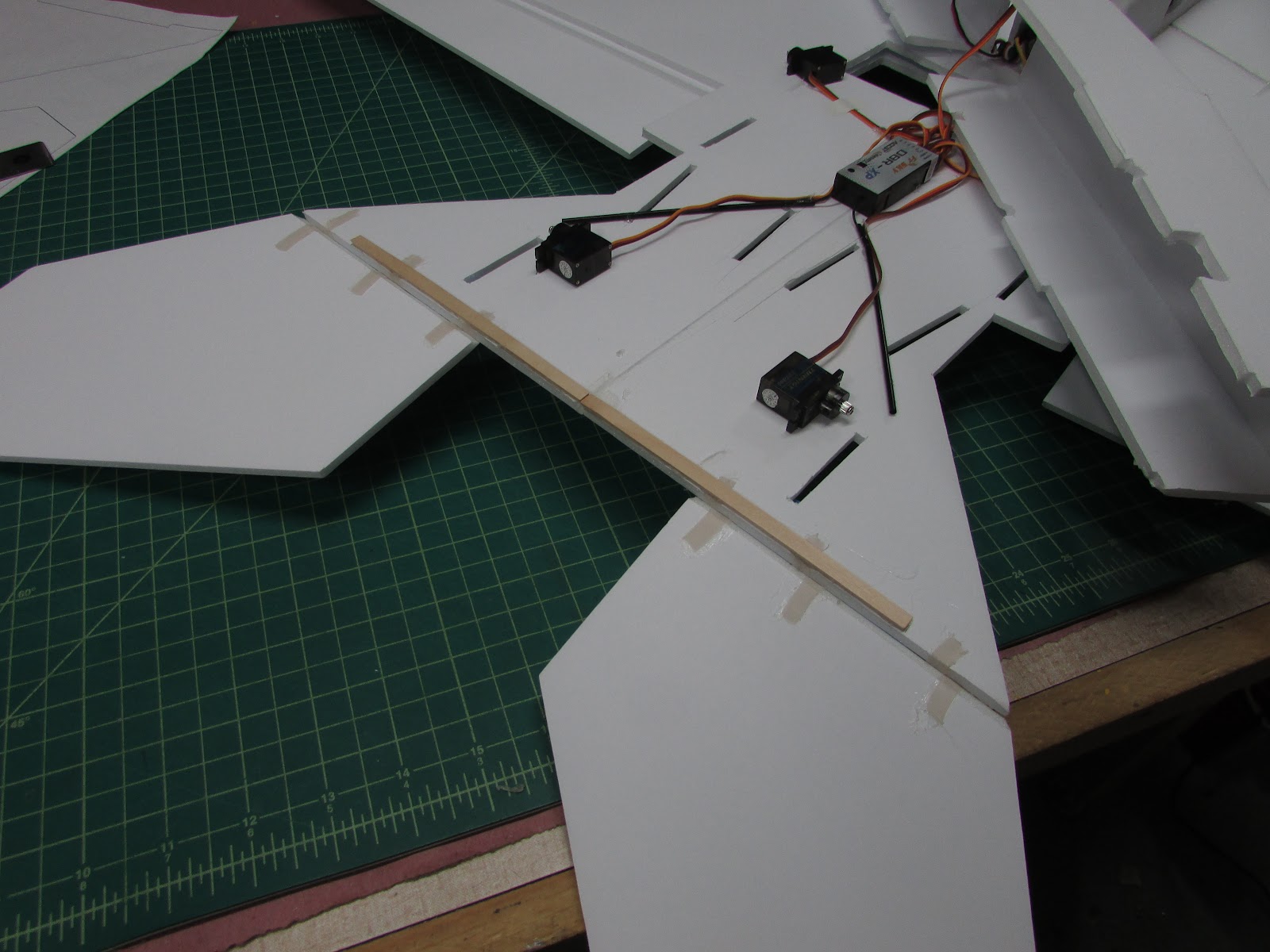
Well, as luck would have it, the tail is a bit flimsy to hold the elevons. The model slipped off the table and hit the ground… and the tail folded. So, I added some wood to strengthen the tail.
Connect control rods from the servos to the ailerons and elevons.
Attach the vertical stabilizers.

To make a nice flush joint with the tail, bevel cut along the inside of the vertical stabilizer. Also, if you want to round the leading edge, now is a great time to so that. Glue them into the tab holes using the angle template to hold the proper angle.

Like the Supersized FT-22, I think the vertical stabilizers should be reinforced to prevent them from folding during flight. I used a skewer to poke a hole through foam board at the front of the stabilizers and

continue the hole through the nacelles.

I used a 3 mm carbon fiber tube for this, but anything long and skinny would probably work - so if you don’t have carbon tube, use a skewer.
Engine Nozzles
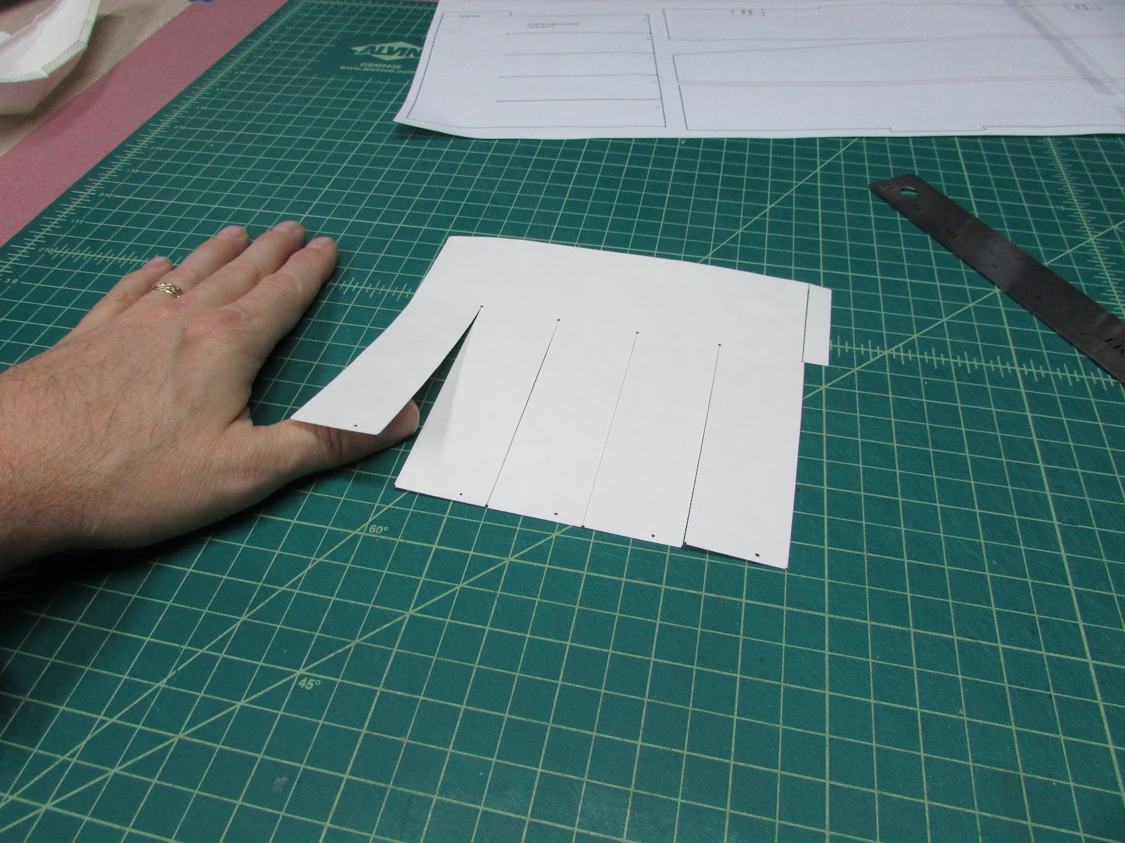
Cut the exhaust nozzles from card stock.

Cut along the solid lines and then roll into a circle and glue along the dotted line (the little tab should be the only thing holding it in a circle).

Glue the rear nozzle overlapping each segment by 1 cm. These can be squeezed into the square nacelles.

Paint them black and then glue the exhaust nozzles into the nacelles by sliding them into the nacelle,

run a bead of glue around the engine nozzles and slide them into place.
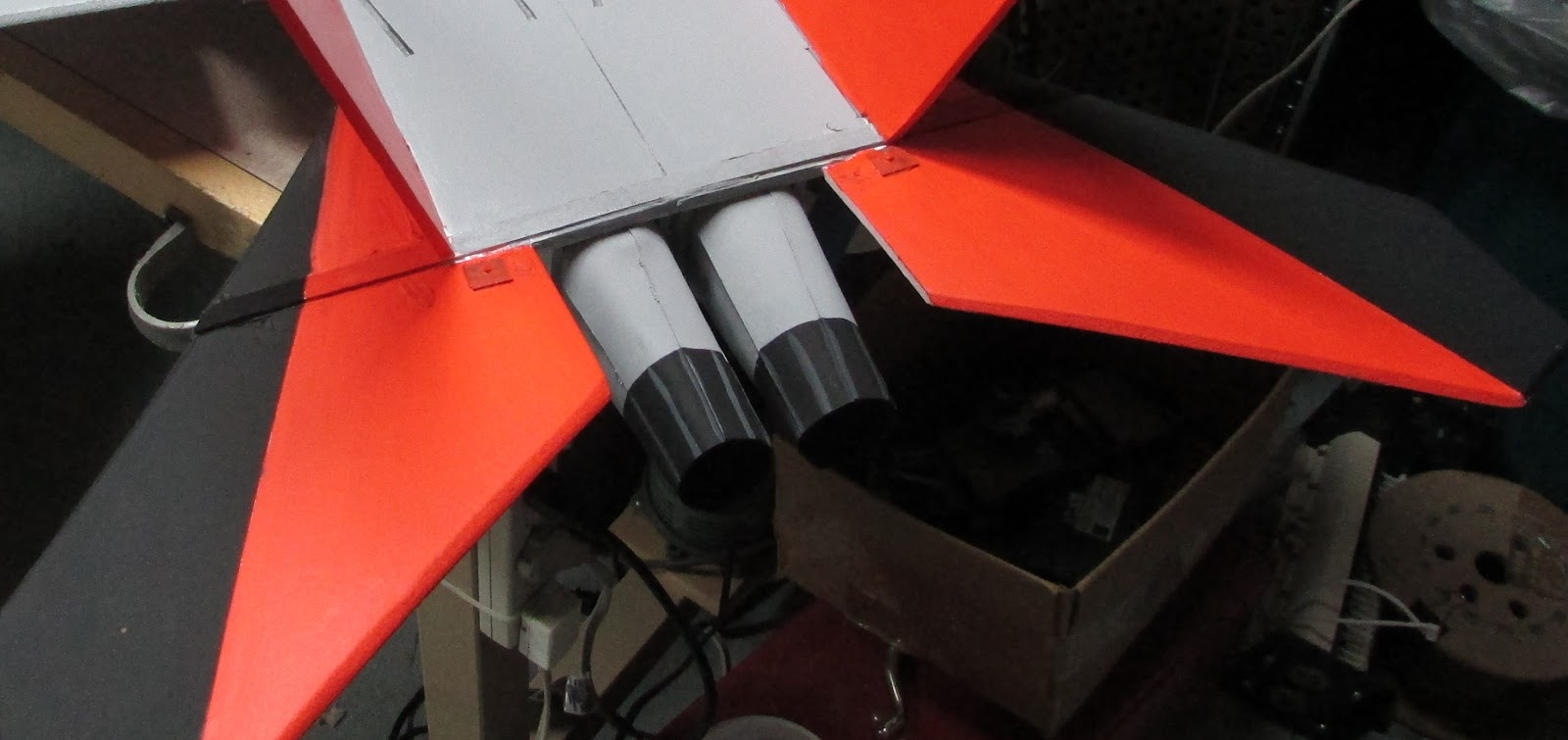
Here is how they turned out after repainting.
Leading Edge Dogtooth
No F/A-18 Super Hornet would be complete without the distinctive wing tip dogtooth edge. Since the leading edge of the wings were used to join the upper and lower wing panels together, we’ll have to just add the leading edge dogtooth as an afterthought. In future plans, I may follow the lead of others by making the bottom wing panel shorter and just cutting the dogtooth into the upper wing panel. But for now, this is what I did.

Score cut a piece of foam and fold it onto itself. Bevel cut the edges along the both sides of the fold. I like resting the foam against the edge of my build table and sliding the blade’s handle along the top of the table to stabilize it while running it through the foam.

Like cutting the spar, while it is doubled onto itself, cut a 1.5 cm strip pushing your knife through both layers of foam.

The end result is a strip of foam 3 cm wide with a “V” notch in the middle when it is laid flat.

With the notch facing the build table, bevel cut the outside edges. Because the foam strip is so thin, I use a ruler to put a little more distance between my fingers and the blade.

Angle cut both tips and then bevel cut the outside edges.

When glued they form a concave “V” on the rear to fit around the wing’s leading edge and a convex “V” on the front that can be sanded to a rounded point.

Glue them as parallel as you can with the bottom panel of the wing.

To get the dog tooth’s parallel to the bottom wing panel, I use a scrap piece of foam as a guide to extend the bottom wing panel.
Glue in place with the tip being flush with the wing tip.

Wing Tip and Weapon Rail
The position of the wing tip rail is a little precarious, especially for those of us who fly and land on grass fields. A little foam rail is just too flimsy to withstand even the slightest bump, so I beefed it up with a little balsa. Even so, I expect that the wing tip rail will break sooner or later so I didn’t want to hard mount it (i.e. glue it to the wing tip). So, I devised a system for removal so that it can be easily replaced after breaking.

First, if the wing tip isn’t flat, use a sanding block to make it so.

I cut out a wing tip cap out of card stock. Before gluing it on, however, if you want the ability to secure the rail with a magnet or a twist tie, those need to be attached before you glue it to the plane. Glue or tape the twist tie to the inside of the wing tip cover and then glue the tip cover in place.

The rail is made with a little strip of foam and balsa on the outside.

Toothpicks are pressed and glue into the foam.

Pressed into the wing.

There - a non-permanent wing tip rail. The rail can be tacked on with hot glue or twist tie. I have used a drop of hot glue

I like all leading edges to be pointed or rounded off. With a few strokes of sandpaper, the leading edge extensions can be sanded into a rounded point. The same can be done for the elevator and vertical stabilizers.
Weapon Positions (supplementary adornments)
The F/A-18 Super Hornet is equipped with a wing tip, 3 mid-wing and one fuselage hardpoints for weapon or fuel drop tank attachment. Although adding these is totally optional, it sure looks cool. Because I have a high suspicion that adding mock weapons to the plane will severely decrease flight performance, I wanted them to be removable (not in-flight droppable- rats). To make the hard points, I just used a scrap foam and cut it to a shape in the plans or make your own design. To make all the hard points interchangeable to other spots on the wing, I made a little jig out of foam and a couple of toothpicks. Align and poke holes in the mount and glue in 2 to 3 cm long toothpicks.
Poke holes in the wing at 16, 24, 32 cm from the wing tip. I used a magnet to hold the weapons to the plane and a group of 5 staples in the hardmount. Now they pop on and off. Now you can glue whatever type of pseudo weapons you want.
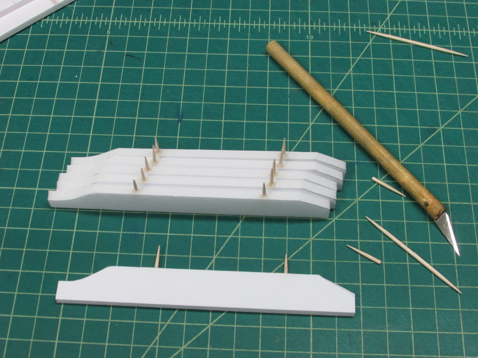
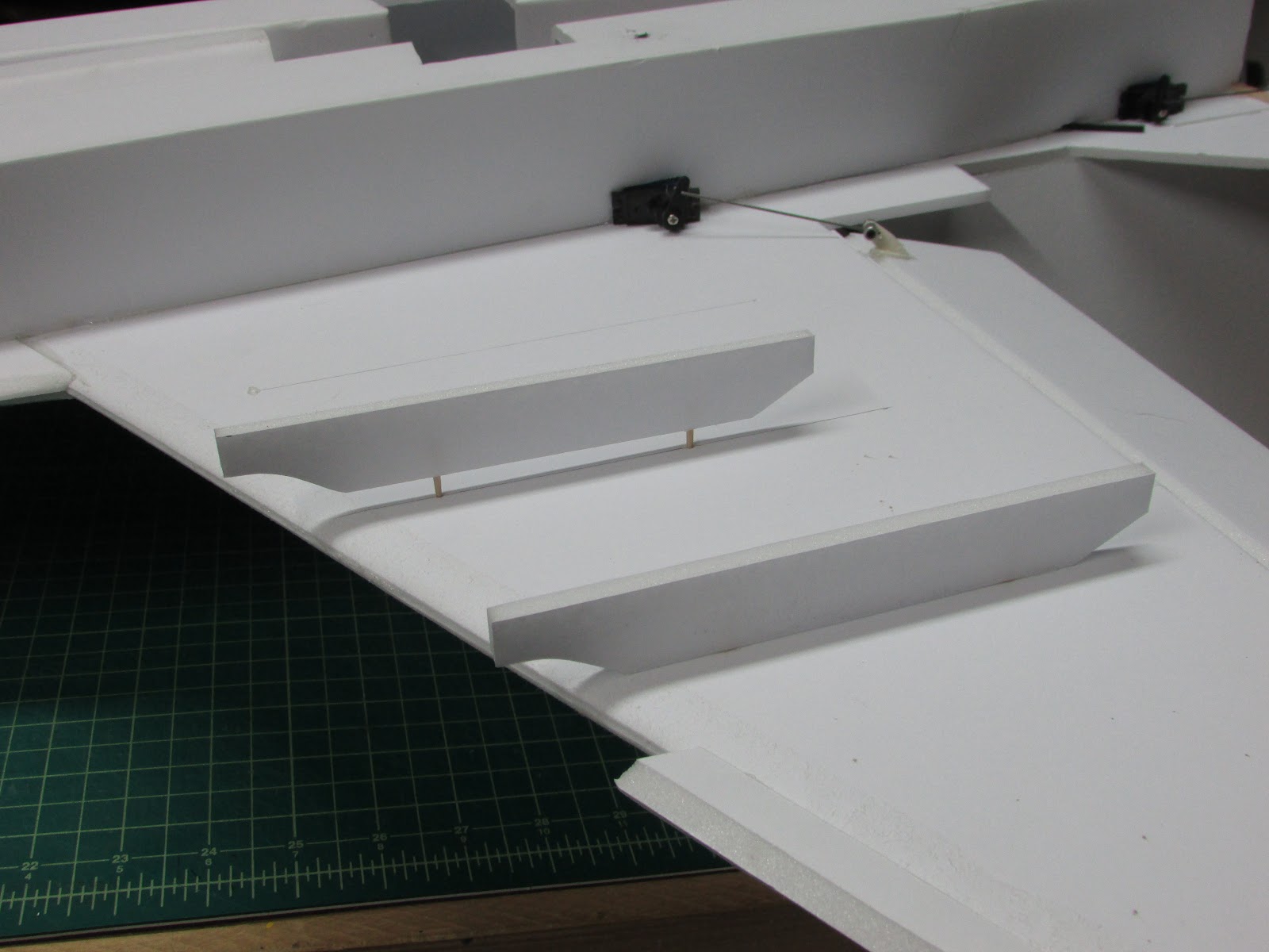
Here I show how the hardpoints are attached to the underside of the wing.


Painting
Spent some time mixing colors to get what I liked. For the military grey I chose a 10:1 mixture of Snow White and Black.

Parts/Materials
- Foam Core - Ross (Walmart)
- Poster board (card stock) (Dollar Tree)
- Battery - 2200 mAh 3S LiPo (Hobby King)
- ESC - 60 Amp Turnigy Plush (Hobby King)
- Motor - NTM 2836 2200 kv (Hobby King)
- APC 7x6 propeller - (Radical RC)
- Servos - Four 9 gram servos (Hobby King)
- Barbeque skewers (Walmart)
- Paint: Acrylic art paint (Walmart)
Free Plans F/A-18 E Super Hornet Supersized
Stats
- Weight (without battery): 1 lb, 8.5 oz (695 g)
- The battery adds 7 oz (196 g) for a flight weight of 1 lb 15.5 oz.
- Wingspan 39” (100 cm)
- Thrust - 40 oz at full throttle. Thrust:Weight ratio 1.21.
HilldaFlyer - March 2016
*******************************************************************************
Appendix:
Designing and building a model takes a lot of trial and error and rebuilding, redesigning and trying again. Here is the extra content, the behind the scenes work.
The first wing prototype and a few of the fuselage designs I tried.

I tried several times to get a completely round fuselage by removing the paper and creasing the foam every 1 cm.

I have to admit that it was really hard getting this shape to be uniform.

But after multiple attempts I got them looking pretty good. It just wasn’t repeatable and forming the nose cone was a real challenge.

The canopy went through several design phases.

Designing the nacelles also took a few iterations. The first design, which I may revisit, was to have the nacelle sides at an angle to the wing. I decided against this more real looking design because it is hard getting the angles on both side cheeks the same.

Getting the leading edge extensions aligned with the fuselage and leading edge was a chore, so I decided to add tabs and tab holes to one of the panels to prevent misalignment.

In my first attempts at forming the fuselage in the octagon shape, I glued the formers into place and then tried to glue it all at once. I just wasn’t fast enough to get the glue on all the formers.

Prototype II, the wing slot wasn’t tall enough and the fuselage was stressed.
Prototype II balancing. That is placing the motor at the end of the fuselage as planned, but I forgot about the wing spar being there.

I had planned on the propeller slot being place right behind the fuselage - you can see the lines where it was supposed to go. Turned out that the motor mount in the wing would have cut the spar in half. I didn’t like that idea, so I moved the motor back 5 cm… and the battery forward about 8 cm.

Prototype III was completed

Weighing in at 1 lb 8.5 oz without the battery.


Log In to reply
Great job man on the design, article, video, and maiden. 1st class all the way.
I like that this bird appears to be able to fly quite slowly. I like that.
Log In to reply
Log In to reply
Log In to reply