Formica-Tri Stubby
by HilldaFlyer May 2015
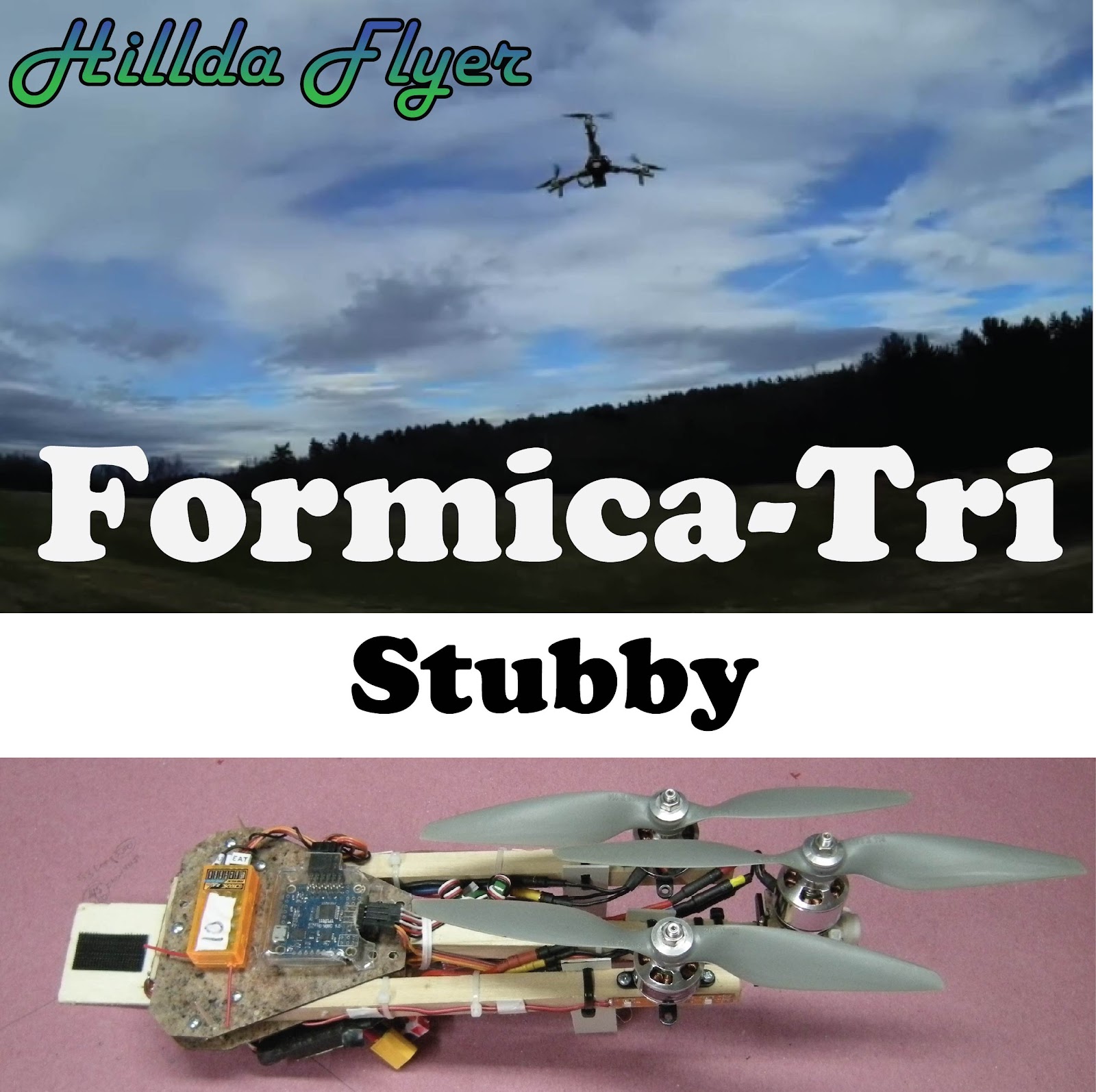
After building a couple of tricopters (Formica-Tri http://flitetest.com/articles/formica-tri) , I wanted to make something smaller… the result was the “Stubby” a tricopter with shorter booms, basically- cut in half. I wanted to make a smaller version so it would be lighter, easier to transport, have less boom flex for more aggressive flight.
One of the benefits of the shorter booms… the ESCs required no modification to get the wires to the control board or power from the battery. If I were to build another Stubby, I would probably shorten the booms by another 1 to 2 cm to give a little more play in the wiring.
Materials:
- Formica - leftover from kitchen construction.
- Epoxy Resin or similar glue - 635 Thin Epoxy System with medium hardener from US Composites http://www.uscomposites.com.
- Saw to cut formica (scroll saw, jig saw with fine teeth 20/inch) or utility knife and straightedge.
- #6 bolts and #6 lock nuts or regular nuts with locktight.
- Drill and/or drill press, 7/64” and ⅛” drill.
- ½” square dowel 1 yard (x2) - local hardware store.
- 4mm Carbon Fiber rod or tube (Radical RC).
- Front Wheel Steering Arm & Mount Set 40mm - Hobby King.
- Turnigy MG90S 9g Digital Metal Gear Servo - Hobby King.
Electronics:
- MultiWii flip 1.5 - Ready to Fly Quads.
- 3 ESC (HK 20A flashed SimonK) - Hobby King.
- 3 Motors Turnigy SK3 2826 1240 kv, Hobby King
- 3 APC 8x4.5 multirotor props - Radical RC.
- OrangeRx DSMX receiver.
Making the body
Make 2 ply formica by gluing two sheets of formica together back to back with epoxy or similar glue. I use epoxy resin from US Composites 635 with medium hardener because it is thin and easy to spread. Use lots of weight or vacuum bagging to hold the sheets together while curing overnight. To get the top and bottom body plates near identical, I cut them out and drill the holes while they are together. To accomplish this, I hot glue two of the 2 ply formica sheets together so that they are one unit. A tip is to warm up both pieces of 2 ply formica with a hair dryer so the hot glue stays pliable longer.

Glue the paper pattern to the formica with glue stick or elmer’s. Cut out the pattern with a saw - I use a scroll saw with 15 to 20 teeth per inch. The goal in all of this is to have top and bottom plates firmly glued together to drill the holes. In all honesty, it doesn’t matter if the edges or shape of the bodies don’t match, but the holes must be aligned to get the booms to be straight.
Plans: Formica-Tri Stubby Body Plans
Cutting Formica without a saw.
Don’t have a saw - no problem. I have been able to successfully break a single thickness of formica in a straight line by scoring it a couple of times with a utility knife and bending the score over the edge of a table. Make four copies and then glue two back to back with epoxy. After curing, glue the 2 ply formica together with hot glue aligning the edges. Sand all the edges smooth and proceed to drill the holes. I have also succeeded in cutting 2 ply formica with a utility knife and straightedge by scoring both sides (5 to 6 strokes) and then breaking over the edge of a table.

To get the holes drilled in the right spot, I use a punch to divit the formica so the drill bit doesn’t skitter around on the surface. After drilling the holes, separate the top body plate from the bottom body plate by putting a few drops of alcohol between the layers. The hot glue peels away from the formica. Alternatively, if you don’t have any alcohol around, warm it with hair dryer for a few minutes. The glue can be removed with a razor blade. The paper template can be removed by moistening it with water. I would like to make a strong recommendation here… get some alcohol. You’d be amazed at how it can be used to remove hot glue from things, like clothes, fingers, velcro, cats… although I haven’t tried the last one yet. I used to spend lots of time picking the hot glue off my fingers, but with a little alcohol, it just peels off. Ok, back to the project.
Making the booms

To the tail boom, mark the placement for the outriggers (½” square 2 cm long) and

glue in place with wood glue.

While those are gluing, using your motor mount as a template, mark the locations of the holes that will hold the motors to the boom. Drill the 7/64” holes. At the other end of the boom, drill a 7/64” hole 2 cm from the end to attach to the body pivot point.

Attach the booms to the body using #6-32 ¾” bolts and locking nuts or regular nuts and thread lock.
Symmetrical motor placement. In all of my tricopter builds, I have placed the motors completely symmetrical using the technique provided by CPO - Symmetrical Tricopter and T-Copter Design Theory.http://flitetest.com/articles/symmetrical-tricopter-and-t-copter-design-theory
The way I’ve done this is Iay out paper on the workbench (the pink stuff you see in the pictures is Red Rosin Medium Weight Paper sold at Home Depot - 36 in. x 167 ft. for $12), lay the tricopter upside down and mark where the front motor shafts touch the paper. Draw an arc using one motor as the anchor point and the other as the radius. Repeat the arc drawing using the other front motor as the pivot point. Where the arcs intersect indicates where along the rear boom to place your tail motor. “X” marks the spot.

Yaw Mechanism
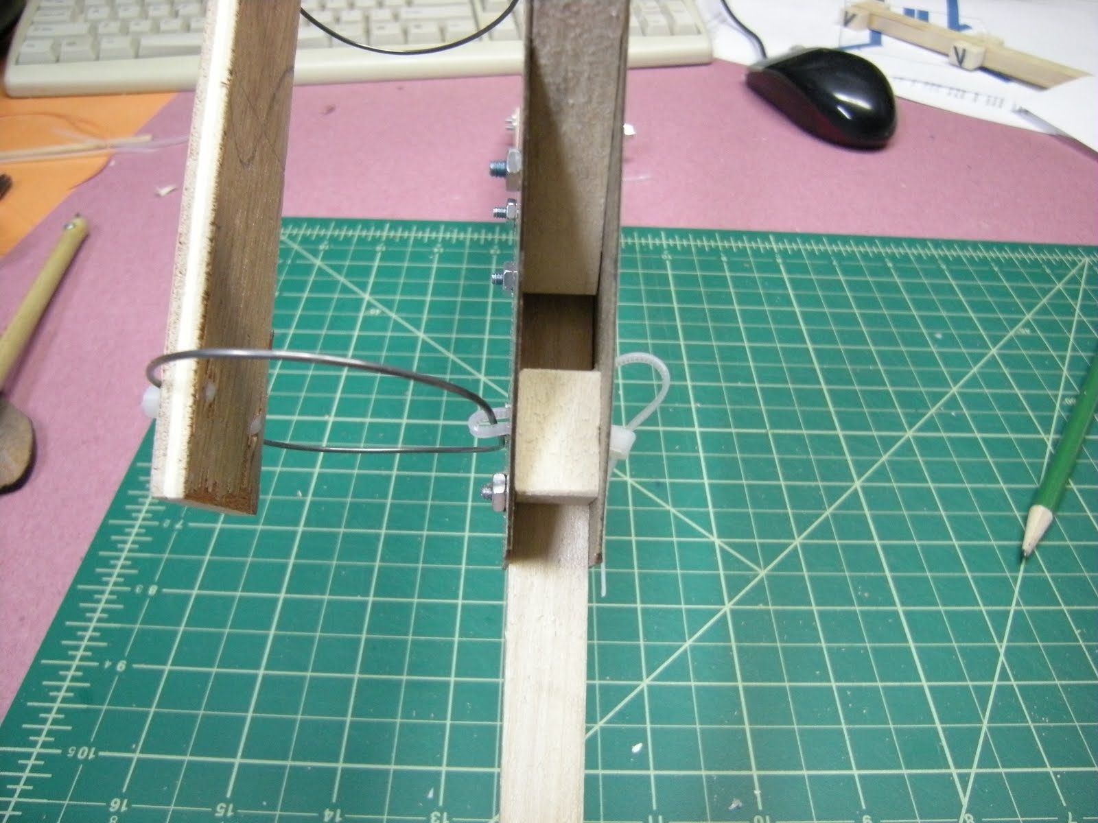
This is what I’ve built. It is fabricated from Front Wheel Steering Arm & Mount demonstrated by David Windestål - with variation. The first thing we have to do is make a hinge with absolutely no extra play and that swings without binding. Others have drilled the holes in the steering assembly larger and use a bolt, but I have chosen to use carbon fiber tube/rod. It is really easy to size and fits like a tight glove. Best of all, being made of carbon, is self-lubricating.

Rather than increasing the diameter of the hole in the steering mechanism, I reduce the diameter of the 4mm carbon fiber tube by sanding with 120 grit sandpaper. Fasten the carbon fiber tube in the drill and while spinning at the fastest speed, slide the sandpaper along the length of the saft. You will really want to do this over a trash can.

Test the size of the tube often so that you don’t make it too small. Sand steering mechanism risers (where the white arches will touch one another) on the inside and outside to create a non-binding fit so that both freely rotate after the rod is slid into place. David has demonstrated the direct-drive system. A small movement in the tail rotor has a profound effect on the yaw rate. To calm down the tail rotor movement with respect to the servo movement, I’ve geared it down by using linkage. First we have to mount a servo arm to the tilt mechanism.

Sand both sides of a servo arm flat and attach it to steering plate with super glue. Use a wire or toothpick to align the servo arm with the center of the hinge. Drill holes through the servo arm and nylon steering hinge (1.5 mm if you are going to use servo screws to attach). Fix the servo arm to the steering hinge with servo screws and put a dab of hot glue on the other side so the carbon rod doesn’t slip out. The ear of the servo arm with the screw needs to be sanded off so that it does not come in contact with the boom.
You will need to make motor mount that joins the steering hinge to the motor. I made some out of 2 ply formica leftover from cutting out the frame.

Draw the shape of the hinge onto a piece of 2 ply formica (or G10 if you have some, 1 ply formica is not strong enough). Draw on the formica where the holes for the steering plate and motor mount. Drill the holes. Use a large drill to add a counter sink for motor mount screws.
To get the steering hinge to hold to the wood boom tightly, the holes in the steering plate need to be elongated. A rotary tool does the job very nicely. After getting done with this method, I realized that you can simply widen the boom with a couple of popsicle sticks so the holes align with the boom.
Attach the yaw mechanism to the boom with wire ties. Attach motor mount plate to yaw mechanism with wire ties. Attach the servo to the underside of the boom with wire ties. To get the servo to be really stable, a piece of popsicle stick was hot glued to the boom to keep the servo from twisting because it is slightly smaller than the boom.
The legs used are 2 ply formica 8 cm long with a single hole 0.5 cm from one end. Secure it to the boom with two wire ties.
Battery hanger and camera tray
The battery hanger and camera tray is pretty much the same type of vibration dampening system used by David, but the following design has fewer bends so it is a little bit easier to make and attach than the wire sandwiched between wood.
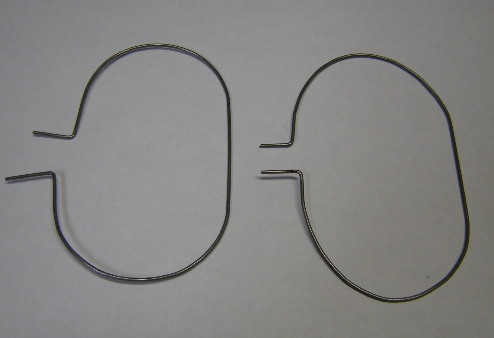
Cut two pieces 25 cm long pieces of .047”piano wire. Mark the wire at 1, 3.5, 10, 15, 21.5 and 24 cm the end. At points 1 cm from each end, bend a 90 degree turn. The next 2.5 cm leave straight and then bend a nice half circle between 3.5 and 10 cm from each end. this will leave a 5 cm straight for mounting the battery/camera tray.

I used a piece of 3 ply plywood from a tangerine box or, as pictured, a piece of flooring underlayment for the battery hanger tray. Feed 3” wire tie through the holes drilled at a diagonal from the wire direction then insert the ends into the center hole in the bottom. Wrap the wire tie around the wire and feed it back through the 45 degree angle hole.

Attach the battery/camera tray to the body using wire ties. Drill a straight hole that aligns with the small hole and an angled hole from the top to the same hole in the bottom.

Insert the ends of the battery/camera tray holder into the small hole.
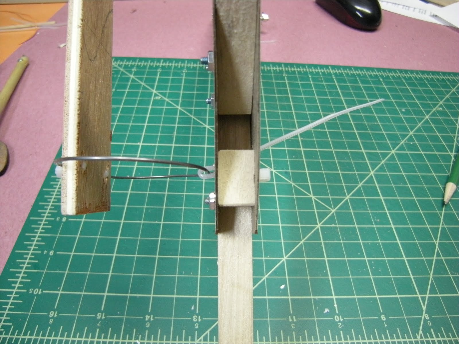
Feed a wire tie from top to bottom, around the tray hanger support back to the top through the angled hole.
Feed it through the clasp and pull tight.

The camera/battery tray is mounted. Attach your motors and feet.

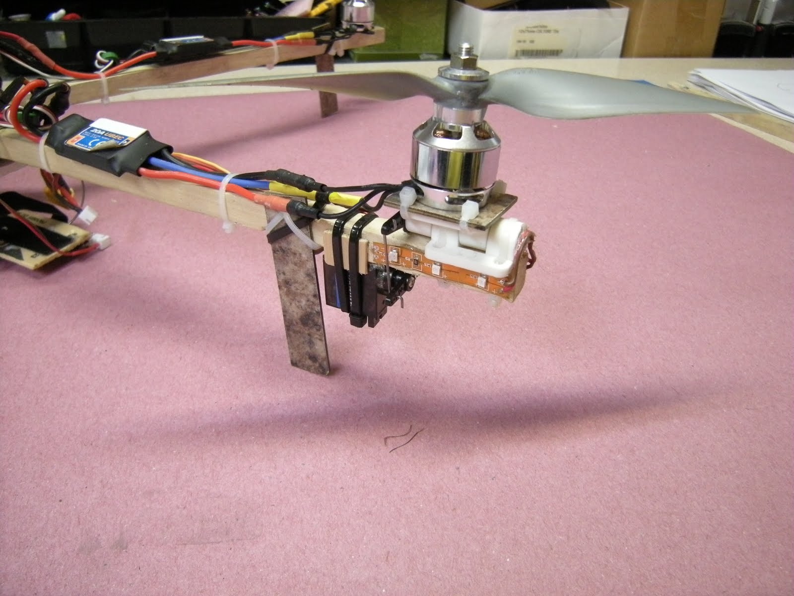
Build the wire harness shown above with your favorite electronics. In this setup I’m using Hobby King 20A ESC flashed with SimonK and Turnigy SK3 2826 1240Kv motors, APC multirotor 8x4.5 props from Radical RC. The flight controller is MultiWii Flip 1.5 from Ready To Fly Quads. Battery 2200mAh 40C.

17 inches from motor to motor.

I mounted the Flip1.5 board on the top with a small piece of foam.

The folding into a nice compact unit.

45 cm in length folded, including the props. Even shorter if you don’t want to mount a camera.
Modification after flight testing.
The first flight was incredibly stable. Without tinkering with the setup, I flew some flights up and down the field.
After dialing in a few adjustments to get the stable mode rock solid, I performed some flips. Back flips were darn easy, however, the roll flips generated enough centrifugal force to swing one of the front arms back on it’s pivot.

To prevent this in the future, I drilled a small hole in the top plate, just big enough for a toothpick and then continued the hole through the dowel.

After swinging the arms into place, I just slip the toothpick into the hole and it holds the arm and prevents it from folding during flight. However, the toothpick breaks like a sheer pin when accidents occur. At one point, I hit the ground and the toothpick broke and the arm folded back. I just replaced the toothpick and I was off flying again.
Battery and Camera Tray - Version 2
You will also notice in these pictures, I’ve changed the vibration dampening tray to be held on with foam ear plugs. They work great, much better than the wire and much easier to assemble.


Mount the earplug by the bolt to the plate. Glue the other end of the earplug to the anchor point.

Maiden flight was at night 3/24/15. I was impressed with the stability of the MultiWii FLIP 1.5.
Tuning on 4/15/15 with flips.


Log In to reply