Build a Tribewt 1
UPDATE 16/01/2015 - Here's links to plans for the 3 'Tribewt' types;
Tribewt Build Sequence
Why build this plane? It's fun and easy to fly - and if you've already built a Baby Blender this build is almost the same.
I had a hankering for a single-wing aircraft, maybe something that looked a bit more like an old-time plane from the 30’s and 40’s. The Baby Blender seemed an obvious place to start. It's a good-sized model, and all the detail for constructing the wing and fuselage is there in the Flite Test videos – it just needed a bit of modifying…
Before starting this new build let’s see what I learned from my original Tribewt.
After some pretty destructive 'testing' I found a couple of weak spots in the fuselage

The first one is just in front of the tail where the horizontal stabiliser stops.

My solution was to insert additional support to bridge the weak point and carry the stresses forward into a wider and deeper part of the fuselage.

There’s another weak spot mid-fuselage. The bend introduced in the build sequence, just behind the cockpit, weakens the foam and was made worse in the original BB design by finishing the swappable pod support along this same line. This abrupt finish to the reinforcement gave a ‘hinge point’ for the forces on the tail to act around. When this area started to show fatigue I repaired it by gluing the crack and adding packing tape.

Later, after seeing the BB2 design modifications, I extended the pod carrier over this weak point.

I also carried a bottom panel (the white bit) over the join. To avoid creating another hinge point I staggered where the new top and bottom supports finish. In this picture you can also see where I removed foam when I shifted the wing back to improve the balance.

This wing modification involved some ‘creative’ work at the front with a second layer of foamboard glued on the outside of the fuselage. You’ll spot some ‘filling’ with hot glue to improve the bedding of the wing. This process involved a thin sheet of baking silicone. I applied a layer of glue to the fuselage, laid on the baking sheet and then pressed the wing into place. The glue set to the shape of the wing and the silicone sheet stopped the wing sticking to the fuselage. I’ve found this flexible silicone sheet has lots of uses when working with hot glue.

This plane flew quite happily on an 8x4 prop with a Turnigy 2730 1500kv Brushless Motor which has a max rating of 8A, but I think it was working a little too hard. I have recently upgraded the motor to the FC 28-22 1200kv Brushless Motor from HobbyKing with a max rating of 14.5A, which works well with an 8x4.5 prop. The other motor is now with my Old Fogey.

I fly a range of planes using 1000mah batteries, but on the Tribewt these could be larger/heavier as I still have this ‘blue tac’ nose weight in the power pod that could be removed.

I modified the landing gear attachment to match the BB2 design with the single cable tie.

The foam wing ends have taken a beating, but have lasted well. If they get worse I’ll cut out the damaged part and insert a repair. These were originally there to extend the wingspan, but they’ve been a real lifesaver - acting as ‘sacrificial protection’ for the foamboard.

Considering the beating it has taken, my dihedral wing design has lasted well and I’m happy reusing it.
So that’s the background. Now, where to begin? First - think about how you want your plane to look.

In this build sequence you’ll see I changed the turtle deck detail to a single seat…
 …but in the previous build it was a two-seater.

Look again at the Baby Blender and you’ll see a third possible layout with a high back to the rear cockpit.
Basically (within limits) you can choose the outline by modifying the heights and profiles of the turtle deck formers and the depth of the fuselage at the nose and tail.
For ease and speed of build, you might even opt for no turtle deck and fly a stripped-down bare-top model with the two servos exposed – in that option I’d deck-over the tail end of the fuselage with foamboard to make up for the strength the turtle deck provides.
If you want to make the plane from a single sheet of A1 foamboard, the fuselage depth has to be reduced from the BB original. I found that at 70mm the power pod slips neatly over the inset wing. This build is based on that fuselage depth. Also, to cover the swappable pod, the nose needs a minimum depth of 40mm. I used this 40mm depth again at the tail as I felt any less would make the tail too weak.
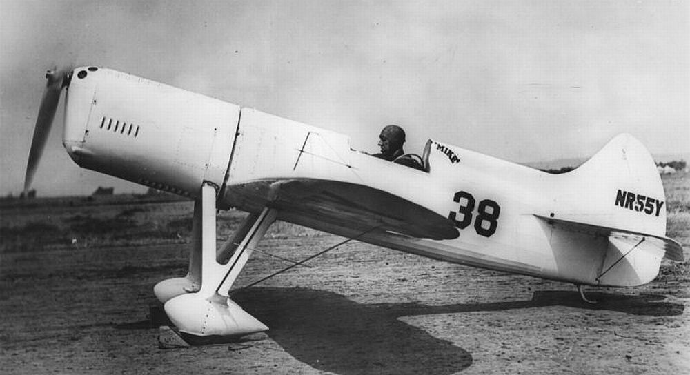
However there is ‘wiggle-room’ at the nose and tail. I tapered the nose on both Tribewts A and B, but you could keep the nose at the full 70mmdepth. For real-life examples of this, look at the Gee Bee model D (http://www.airminded.net/gbsportster/geebee_d.jpg) and the Howard DGA-4 (http://i53.photobucket.com/albums/g64/PoorOldSpike/Photos%20Two/Howard-DGA4.jpg) .
These old designs can influence your choices of fuselage profile - and the shaping of the rudder and elevator. Don’t expect miracles, but a good profile flowing into a curved top section, with a few simple details, like a windscreen and a creative paintjob can produce a very pleasing model.
A lot of those 1930’s racers were one-off’s that were constantly being modified - so nobody can point a finger and say that’s not right.

I did wonder how this plane might look if I used the high BB turtle deck former, but instead of sloping it back as much I ran it almost straight across and merged it into the vertical stabiliser? If you want that, you’ll need to think about it at this stage!

Curiosity got the better of me - this is what it would look like. VERY roughly based on a GEE BEE sportster. I'd want a different wing shape, with more curve at the tips to improve the look. UPDATE - this plane is now flying - see link at bottom of page.
Preparing the pieces.

Here’s a very rough cutting guide for where I placed the components on the A1sheet.
The wing uses a panel 700mm x 368mm. Don’t bother about the full-length internal spar - ignore this just now. It’s cut in shorter lengths from the side of the sheet.

The wing uses the BB1 wing folding detail but is extended to 70cm wide, with modification to the aileron dimensions which will be explained later. Ignore that CG, that’s for the Baby Blender.
The fuselage uses a panel 218mm x 548mm
Rudder and tail fit into the bottom right corner, leaving a panel above it for various components like the wing spar. There’s also useable material in the fuselage area.

The rudder and elevator are straight from the BB - print them up and then decide what shape you want yours to be, sketching curves within the outline...

…though you’ll need to reduce the WIDTH of the horizontal stabiliser to keep it on the A1 ‘page’. I used a width of 280mm, which looks about right on the finished plane. In the picture you can see the end of the fuselage just overlapping the original BB elevator. All the hinge lines are correct, as is the detail for the cut-outs in the rudder. Other than this limitation don’t worry if you go slightly ‘outside the templates’ to get the shape you want. I think the US foamboard is larger, so that might allow easier fitting of the components.

In line with the BB2 detail I modified the rudder to add a strengthening ‘keel’ and a locating tab. If you print-up the BB2 plans to work from, this detail is already there. You'll need to match the depth of the keel to the new fuselage depth - this is explained in more detail later. I also left a small overlap at the front of my rudder so that I could locate it in the last little turtle deck former. (Check the fuselage build for this detail before cutting out. Not important if you follow the BB2 build sequence.)
Cut carefully and don’t waste material! We’ll use up that spare foamboard as we go along.
Start with the Wing.
Cut your wing build panel from the main sheet and then put a centreline on both sides of the panel. Mark up the folds, the half depth cut line for the leading edge and the positioning marks for the spar.

Note the modification of the ailerons. You can carry them full width if you want but I felt the shared servo, linkages and horns were working hard enough, and I didn’t want to push it. However, if you intend to shape the wing through the aileron, reducing its area, then it should be no problem to go full width with the hinge.
That’s the marking-out done, so now to build the wing.

Make the half depth cut for the leading edge of the wing, fold it back and bevel each side (basically follow the BB build video). Score the fold lines and then ease the wing into shape making sure that the whole wing curves evenly. Don’t glue the leading edge yet! Cut the deep bevel on the inside of the wing top. At this stage you can split the TOP of the wing down the centreline.

Now crease the paper down the centreline on the inside of the bottom of the wing and gently bend it to form a shallow dihedral.

Now to make up the dihedral spar. I use a 300mm length of 2.3 mm piano wire. I reckon as thin as 2mm would work, but I liked the ‘stiffness’ of the 2.3 wire.

Bend the wire in the centre to create a shallow angle. That’s the end raised about 25mmfrom the level.

Prepare a 300mm length of foamboard spar – make it slightly wider than the BB spar, 14mm is good, and cut a double-width piece to make sure the spar doesn’t fall apart during the next stage. Mark a centre line, and cut the paper only down this centreline, this is not a half-depth cut.

Run the end of a skewer down the cut...

…and againg, and again, gradually increasing the depth of the impression…

…until the wire can fit snugly without projecting too much above the foamboard.

Split the spar off from the adjacent spar piece – and get ready to build your foam and wire sandwich.

I’m adding a couple of lollipop (popsicle) sticks at right angles to the end of the wire to spread any concentration of load across the wing. Cut two of them roughly 100mm long. I couldn’t find my narrow sticks, so ended up using these wider ones – narrow ones will do though.

These sticks are ‘checked-in’ at both ends of the spar so that the wire sits right on top of them. After cutting the paper I pared away a little ledge with the craft knife, shaving it down to get a neat fit.

Dent the midpoint of the foam spar, it’ll help you align the wire when you fit it.

Here’s a dry assembly showing the components in their proper arrangement. The popsicle sticks need to fit within the width of the wing – make sure they don’t catch the front of the wing or stop the top folding down properly.

Glue the wire into the depression in the spar.

I did this in two stages - left then right. When gluing the first end it’s important to keep the bend in the wire from dropping from the vertical. After applying the glue I positioned the wire in the slot, laid a sheet of baking silicone over the ‘hot’ half and then pressed down firmly with a length of wood to make sure the wire was well sunk into the foam. When it was cool, I rocked the assembly over and repeated for the other side.

Now fit the dihedral former components to ONE SIDE of the wing. Make sure the dihedral bend falls on the centreline of the wing and test-fit it to find where the popsicle stick needs to be positioned. Glue the stick in place, then glue the spar in place. Use the front spar guidelines already drawn on the wing. Butt another length of spar onto the end, fitting it around the popsicle stick if necessary.

Glue on a second layer of spar material - overlapping the join. Press down firmly to make sure the wire is completely enclosed. Where the second layer of spar crosses the centre of the wing, dent the paper to allow it to bend.

Finally, glue down this side of the wing.

Repeat the spar assembly on the other half of the wing.

Before folding over the top of the wing and gluing this half you need to remove some material from where the two wing halves meet. Almost nothing where the wing is thinnest to about 2mm where the wing is fattest.

Removing this material allows the wing to form the dihedral angle already set by the wire. At this stage don’t force anything or you'll reduce the dihedral. Just sand or pare with a craft knife until the second half of the wing drops into place. When it’s a good fit, fold the wing top over and glue into place. Concentrate on establishing a good matching wing profile and don't glue the centre join until the two wing halves are dry.
Once it’s all set, gently ease the centre join open. Just a crack, and run some glue into the gap. Allow the join to spring closed and clear off the excess glue.

Next cut out a 170mm x 60 mm pad.

Mark on a centreline and mark on the fold points that make up the curve of the wing. Make half depth cuts across the pad and spring the cuts open. Glue the pad onto the top of the wing making sure it lines up with the centre of the wing (front and back). This pad centres the wing to the fuselage and also adds strength to the join – so it’s important to get a good bond, and to get it in the right place.
Next stage on the wing build is the foam wingtips, but we’ll do them later as we need the square wing-ends as a template to mark cut-outs on the fuselage.
The Fuselage.

Print yourself up a copy of the BB fuselage, and then we’ll make some modifications.

Reduce the depth of the nose to a minimum of 40mm.

Measure back 100mm from where the swappable pod carrier finishes. Do this on both sides and run a line across both fuselage sides. This marks the front of the wing, and the position of a shallow bend if you want to taper the nose.

Measure up 70mm from the outer ‘A fold’ line that’s already there.

70mm up on the existing bend line where the tail starts to taper.

And 40mm up at the tail from the original BB fuselage detail – if you’re working from the BB2 drawing you need to draw-in the old detail. You can add the lugs if you want. Repeat this for the other fuselage side.

Remember to also use this 40mm depth when drawing out the vertical stabiliser – you don’t want an extra bit hanging out below the fuselage.

You can leave the detail of the pod support extension as BB2 or extend it more like this. I’ve done this for the reasons explained before - as this fuselage is not as deep as the BB I wanted more strength here, so mine has the longer extension.

These are the basic sizes for the Tribewt, but you might want to alter some of them.

You don’t need to taper the nose, but I did. I had to allow room to fit and remove the swappable pod so it can’t be too narrow. Measure in 8mm from the front corner and this should give you enough clearance, unless you built a particularly fat swappable pod.

Draw a line from your mark you just made to the point where the inner ‘A fold’ line and the new crossing line meet.

Add the new lines you measured. I find it helps to scribble over unwanted detail to avoid confusion. The lower half of the fuselage has been cut away to show how it should look. Ignore the servo cut outs, you’ll work out where to put them later.Transfer your template detail to the foamboard and cut it out

You’ll need to ‘ease’ a front and back bend – scoring the paper first. Then fold up and glue the ‘A’ Type bend – but leave the front and back tapering sections dry.

Once you have the basic box you can mark on the cut outs for the wing. Line up the front of the wing 100mm back from the front of the swappable pod mount. You already have this measurement on the inside of the fuselage – just transfer it to the outside.

Mark the wing profile onto the fuselage.

The wing cut out only goes as far as the ailerons. Make a mark here.

Here it is, ready to cut out.

Repeat on the other side.

We’re going to add a little pad behind the wing to stiffen and strengthen the fuselage, and give something solid for the back of the wing to locate against. I’m going to make it end at a different place to where the pod carrier ends. This stops creating another hinge point for the fuselage to fold over. I’ve marked where I'll end my pad - roughly halfway from the bend in the fuselage to where the top support finishes. Use a piece of foamboard to help mark the depth of the cutout. Draw a line from the where the wing ends towards the tail, then tip the fuselage so that the back sits on your work surface and extend the line to where it will finish.

…this gives you the section you need to remove to fit the pad.

Easy enough to work out the size of the pad. Width of the fuselage x length from where the wing finishes to where you decide it will finish.

Mark where the underside of the fuselage changes direction.

Crease and bend your pad.

That’s it ready to be fitted, but we’ll need to get everything true first.

Using the grid on the cutting mat I lined up the fuselage components. I have a centreline on the underside of the pod carrier to help with this. Note the little spacing pads under the tail section to stop the fuselage tipping. I've placed an extra layer of foamboard in the middle at the back where the rudder keel will go - and the middle of this is lined-up on the correct grid line.

If you follow the BB2 construction this isn’t as important, as that assembly self-aligns the tail components. If you haven’t, this is how I did it. With everything in its proper position, I carefully glued that short piece of foam at the bottom onto the fuselage sides and waited for it to set – that meant the angle of the tail was fixed making it much easier to work with.

Now I can fit the reinforcing pad. Make sure the front lines up with the marks you made for where the wing stops

Glue the pad in place and trim away the excess – a sharp kitchen knife is good for this as you can rest the blade against the fuselage side without cutting into it.

Remove the wing cut outs.

Test fit and marvel at your precision!

Now to get the swappable pod fitted – test fit and align the locating lugs. The BB build advice is to make these short until you can fit it to your own pod. Cut the lug slots for your pod.

Here’s the pod in place.

Sort out the position of the skewer mounts.

Fit them!

Here’s my vertical stabiliser. Prepare this and the horizontal stabiliser as the BB build, adding hinges etc.

Do a dry fit and make sure you get adequate movement from both control surfaces on all combinations of movement.

I cut the vertical stabiliser to project slightly over the horizontal stabiliser... (If you like this detail, but didn't allow for it, you can also trim back the horizontal stabiliser.)

…so it would locate in this little turtle deck former.

See how it works.

This helps centre my tail assembly.

It does a similar job to the BB2 locating lugs.

Time to glue it all together. First join the vertical stabiliser to the horizontal stabiliser, checking for a square fit. I then attached my little centring piece to the tail assembly and let it set. I then glued the tail assembly to the fuselage. Finally I glued the pod support extension to the sides.

Then I removed that little brace.

Where I’d identified a weakness, I added a strengthening member which extended over the problem area. Note it’s not on the outer edge, but tucked inside near the middle to make a kind of H section, a bit like a girder.
Note - I still haven’t glued the sides to the top at the nose.
Now we can move to the turtle deck. Look for the next build article - Build a Tribewt 2.
Cheers, Alibopo.


Log In to reply
But seriously, most of the actual build methods are covered in the Flite Test build videos for the 'donor' plane. I'm just trying to show how versatile the build method is. How did Josh describe the Baby Blender when he was introducing the FT Duster - as a kind of Swiss Army Knife. Hopefully there's a few extra bits of information in my articles that you can use in your own builds? Anyway, thanks for the comment - video would be a good way to go, but it's a bit beyond my resources and skill set - so for now it'll just have to be the good old fashioned way. Just think of it as mind calisthenics. :)
Log In to reply
Log In to reply
Log In to reply
Log In to reply