Introduction:
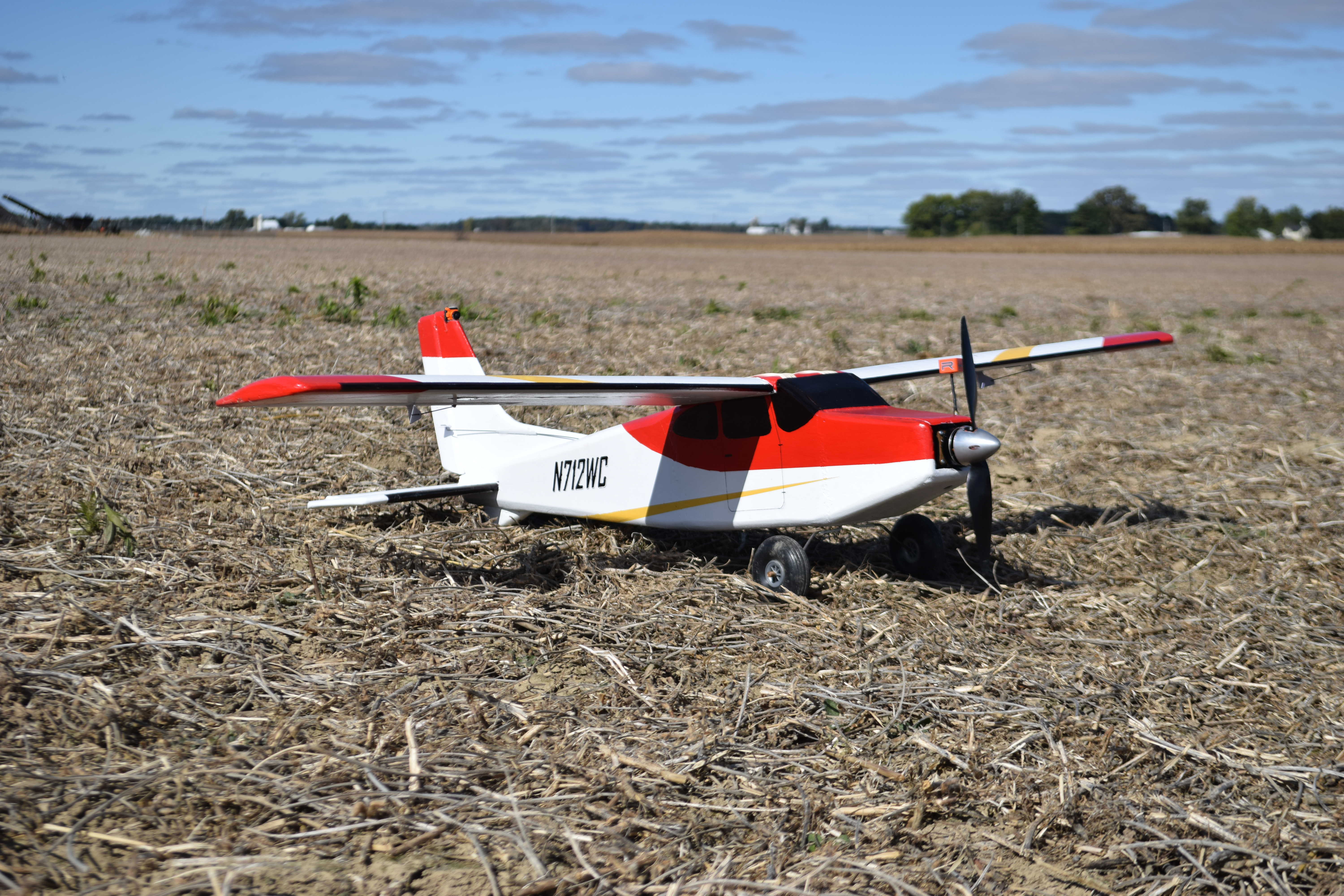
This plane was inspired by many things. The most recent plane I'd made up to this was a small Piper Archer, a rendition of my great grandfathers real plane. This model had a high wing loading, and was prone to stalling and entering into unrecoverable spins, essentially, it flew like a warbird (see article on it: https://www.flitetest.com/articles/scratch-built-piper-archer-ii. I had put a small FPV camera on the tail overlooking the plane, and really enjoyed flying with this perspective. After several crashes with the Archer, I decided it was time to build a bigger plane that could carry the necessary electronics and be able to land, in order to get a full FPV experience. I began thinking of designs, and settled on a high wing "bush" type plane with large tires for landing on all terrains.
Design:
I designed the plane in 3D on my computer using Fusion360. The design went through several iterations, until I got a shape that looked "right." Once I had the 3D design, I used Fusion360 to make 2D side, top, and front views. The final plans can be seen below: *Note, the plans call for a 2206, 2360kv motor and 6in prop, but I ended up using a larger 3506 650kv motor and 11in prop due to balance issues*

FIGURE #1: Final Plans. (Download PDF Here: High Wing FPV Sport Plane.pdf).
In summary, it has a 53inch wingspan with 7.5inch chord, and an all up weigh which ended up being about 1100g.
I started out the design by knowing that the all up weight would probably be about 800-1000g total. This estimate was from experience building similar sized planes. From this "max weight" of 1000g, I used an online wing cube loading calculator(http://www.ef-uk.net/data/wcl.htm) to determine what size wing I should use. I initially chose a 50x7.5inch wing, but once i began construction, I ended up using 2 24" pieces of foam as the wing halves, then the 5" for the fuselage in the center, and wound up with 53 inch wingspan total. This results in a wing area of 397.5 square inches, which when plugged into the wing cube loading calculator with a weight of 1000g resulted in a plane which was in the "Trainer" category, which is good.
I then based the size of the horizontal tailplane by making its area be 1/3 the area of the wing. Then made the vertical tailplane be about 1/2 of the horizontal tailplane's area. I made the total fuselage length be about 75% of the wingspan. I then adjusted the fuselage size until it looked cool.
1.) Fuselage Build:
I started out with a few pieces of 2ft x 2ft x1in foam blocks which I purchased from Home Depot. This is the Owens Corning "Formular" Pink solid foam. I buy the small pre-cut pieces, because a full 8ftx4ft piece will not fit in my car. I began by using my hot wire cutting bow to cut one of these pieces in half which gave me 2 pieces which were 2ftx2ftx0.5in. I used a straight piece of aluminum that has holes in it to be nailed into the foam, and act as a straight edge for the hot wire cutter. 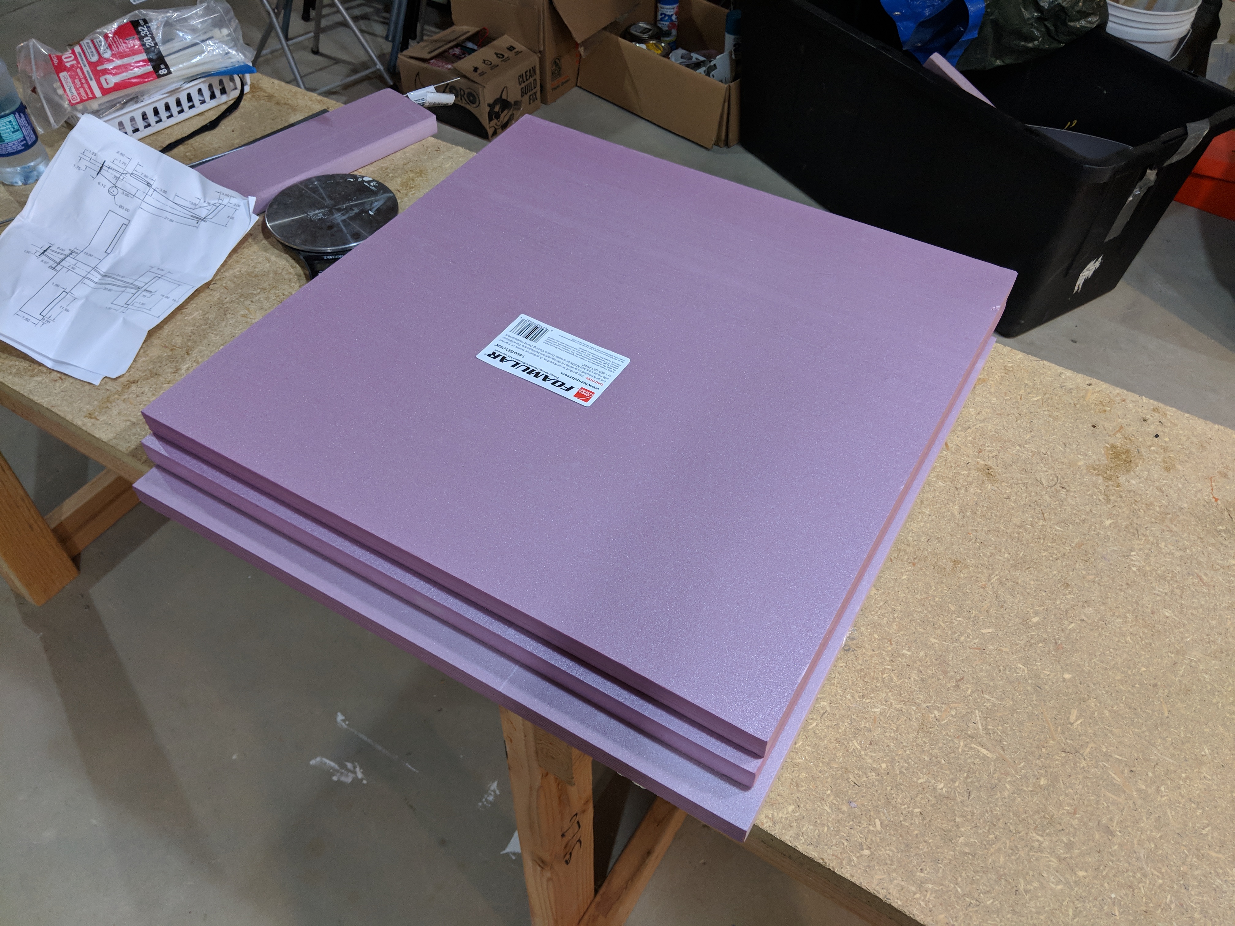
IMAGE #1: 3 pieces of 24"x24"x1" Formular Foam blocks.
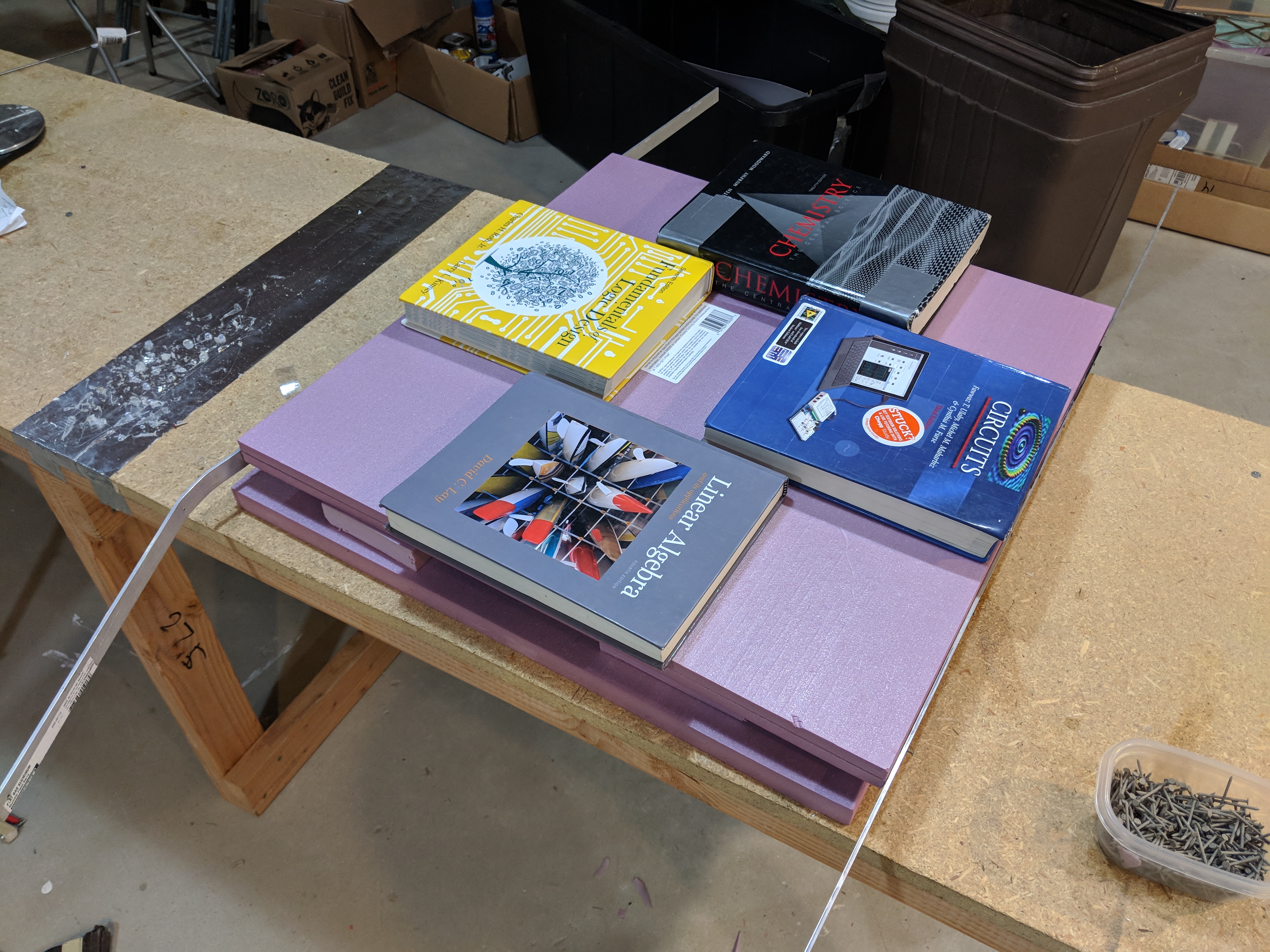
IMAGE #2: Foam blocks with aluminum straight edges on each side, and books to keep it flat.
With the 1/2 inch foam pieces, I began drawing on the individual pieces from the plans for the fuselage walls, floor, and roof. I drew them with a pencil, then cut out with a SHARP hobby knife. I then glued the fuselage pieces together in 3 large sections -the nose, cockpit, and tail. The pieces were held together with masking tape while the gorilla glue dried. Once each section was dried, the ends were sliced off with the hot wire to make a smooth surface for each section to but up against. I again used gorilla glue to glue them together, with masking tape holding them in the right spot. After everything was glued together, and dried, I ripped off the masking tape, and sanded all the edges to give a nice, smooth, and rounded surface.

IMAGE #3: Pieces for the 3 sections - Tail, cockpit, and nose, from left to right.
The fuselage is constructed in 3 separate sections, the nose, tail and cockpit section. These are build using simple shapes to create a box structure.
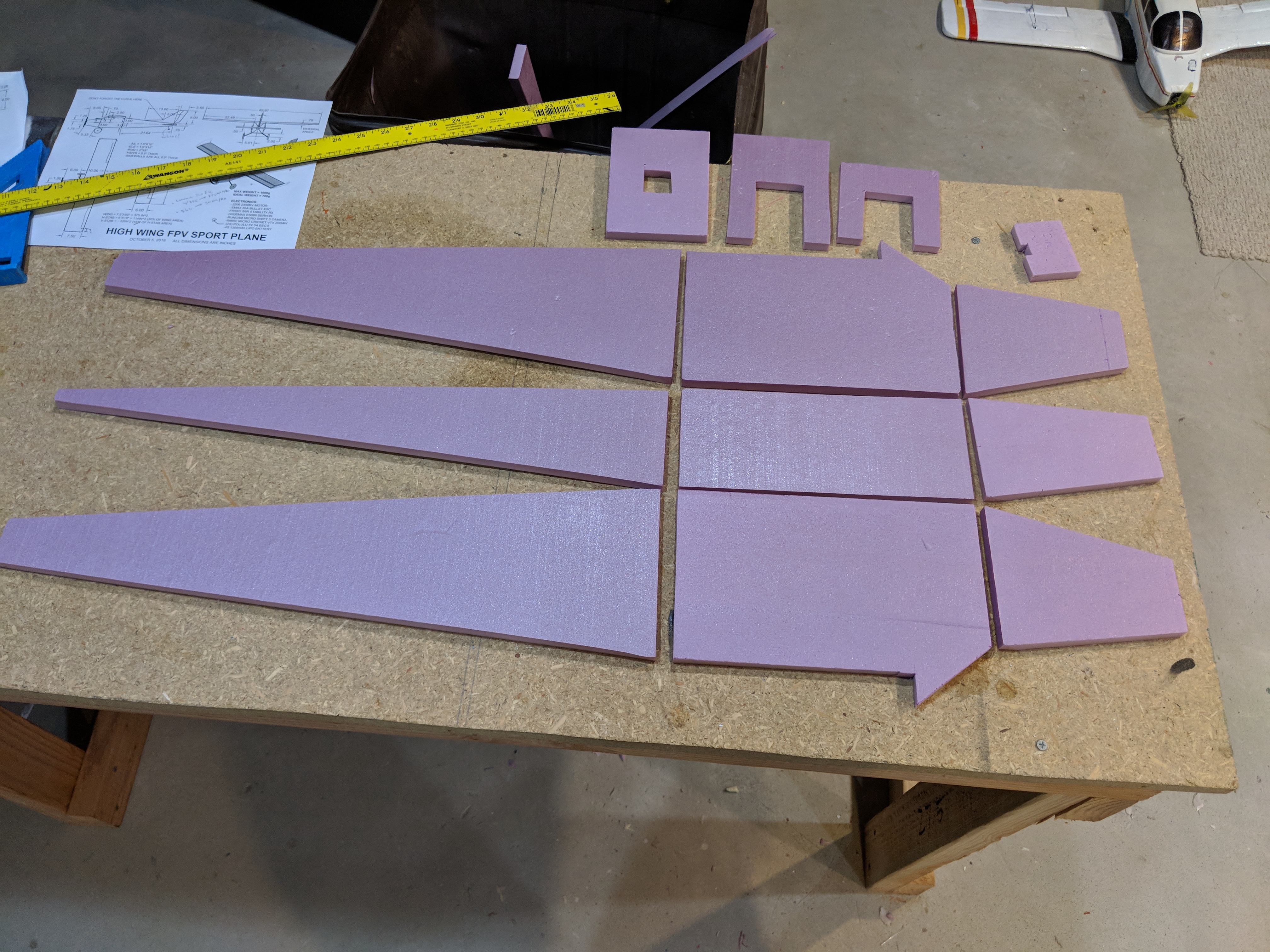
IMAGE #4: Laying out the pieces with bulkheads shown at top.
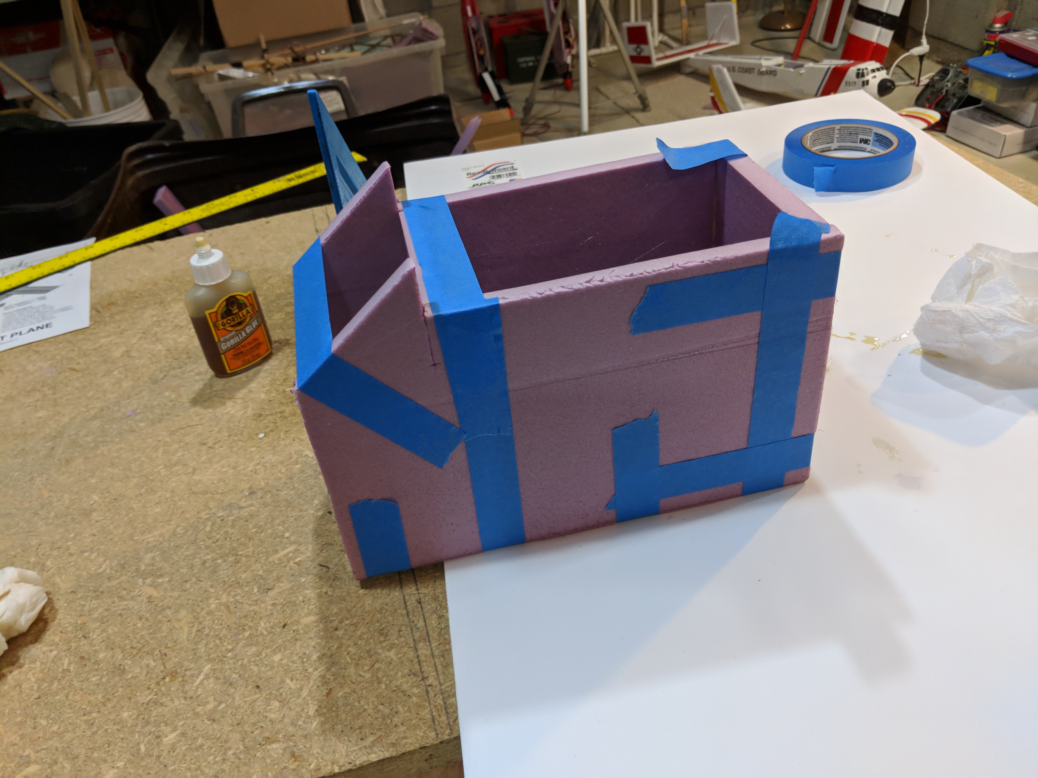
IMAGE #5: Cockpit Section.
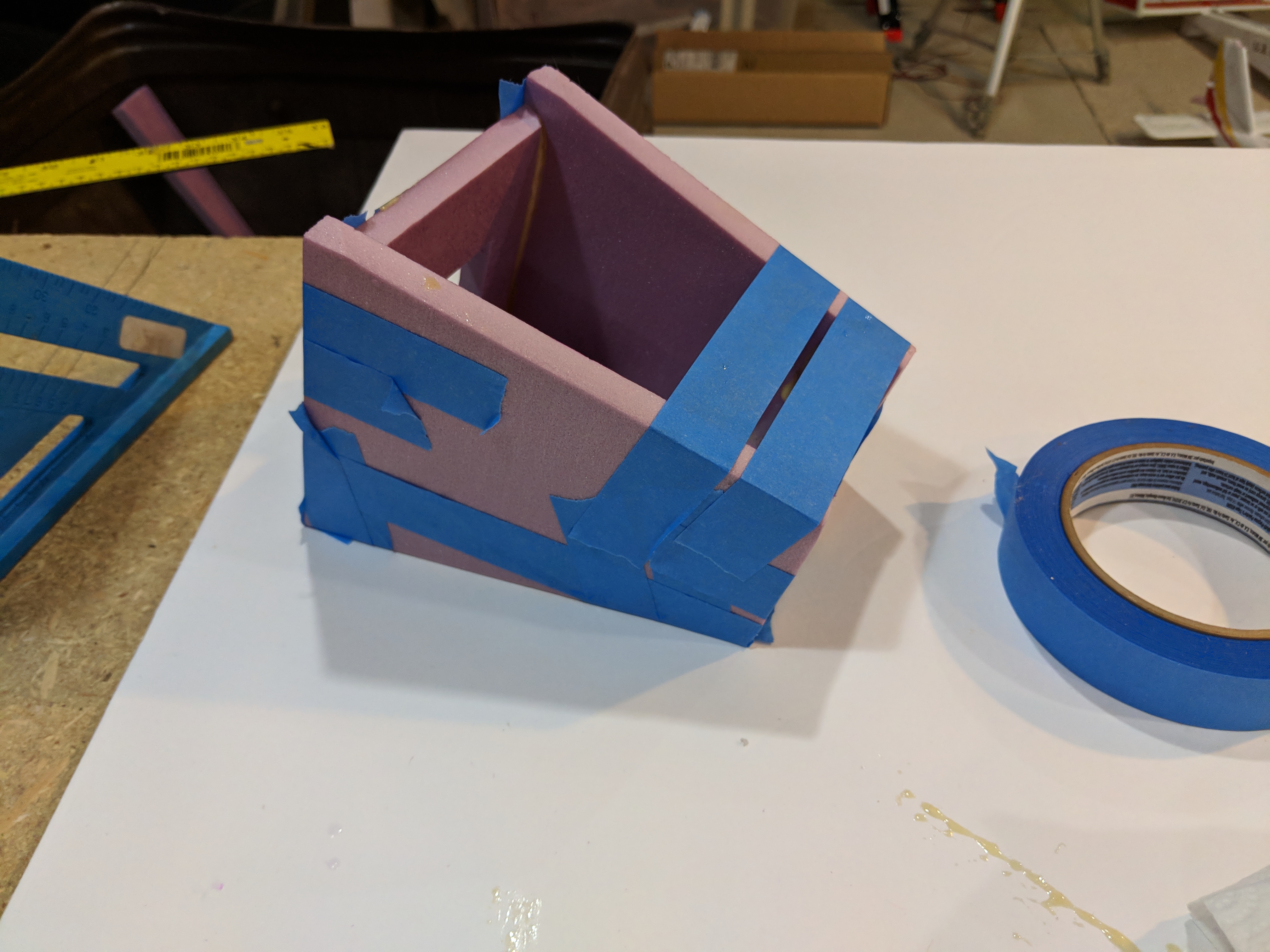
IMAGE #6: Nose Section.
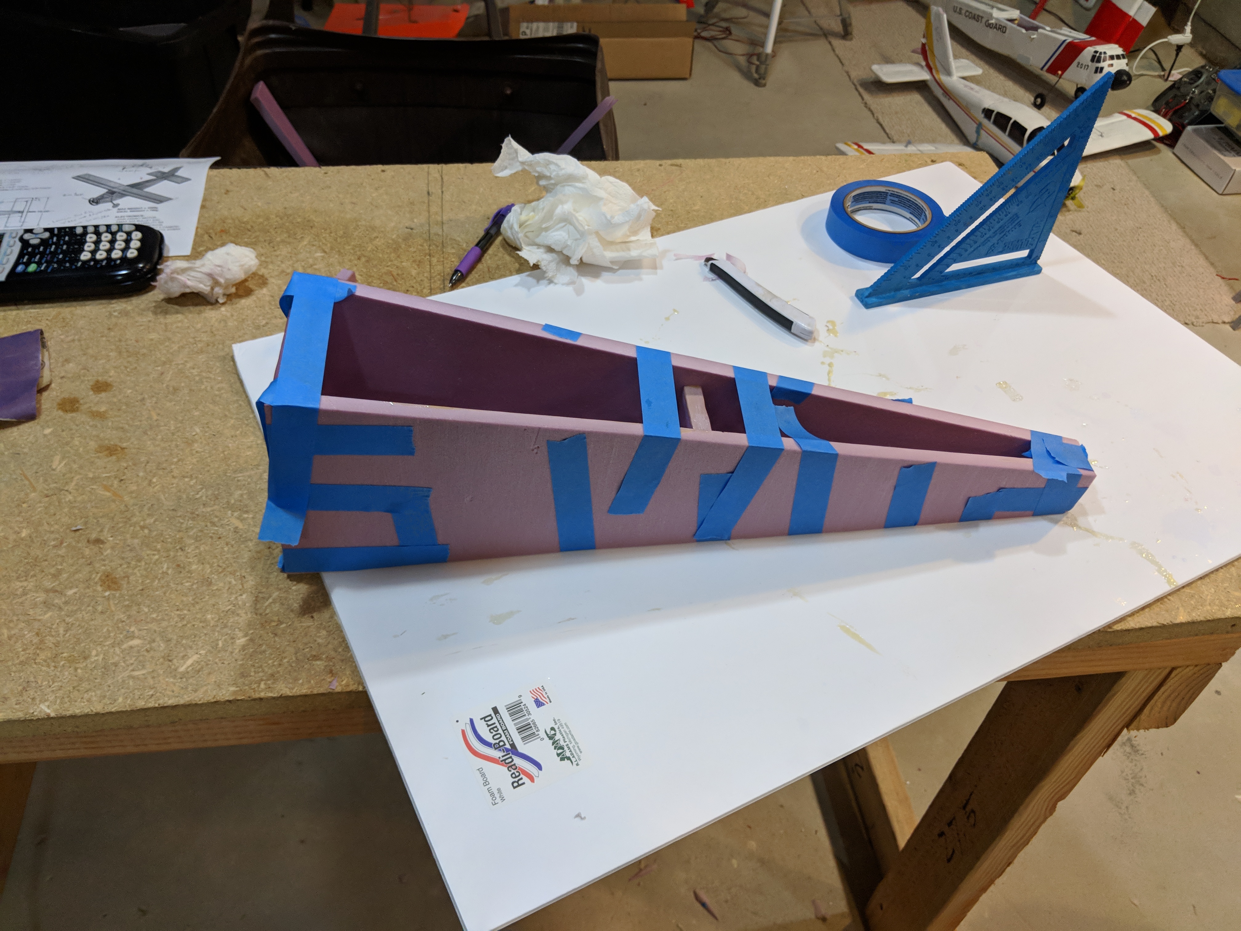
IMAGE #7: Tail Section.
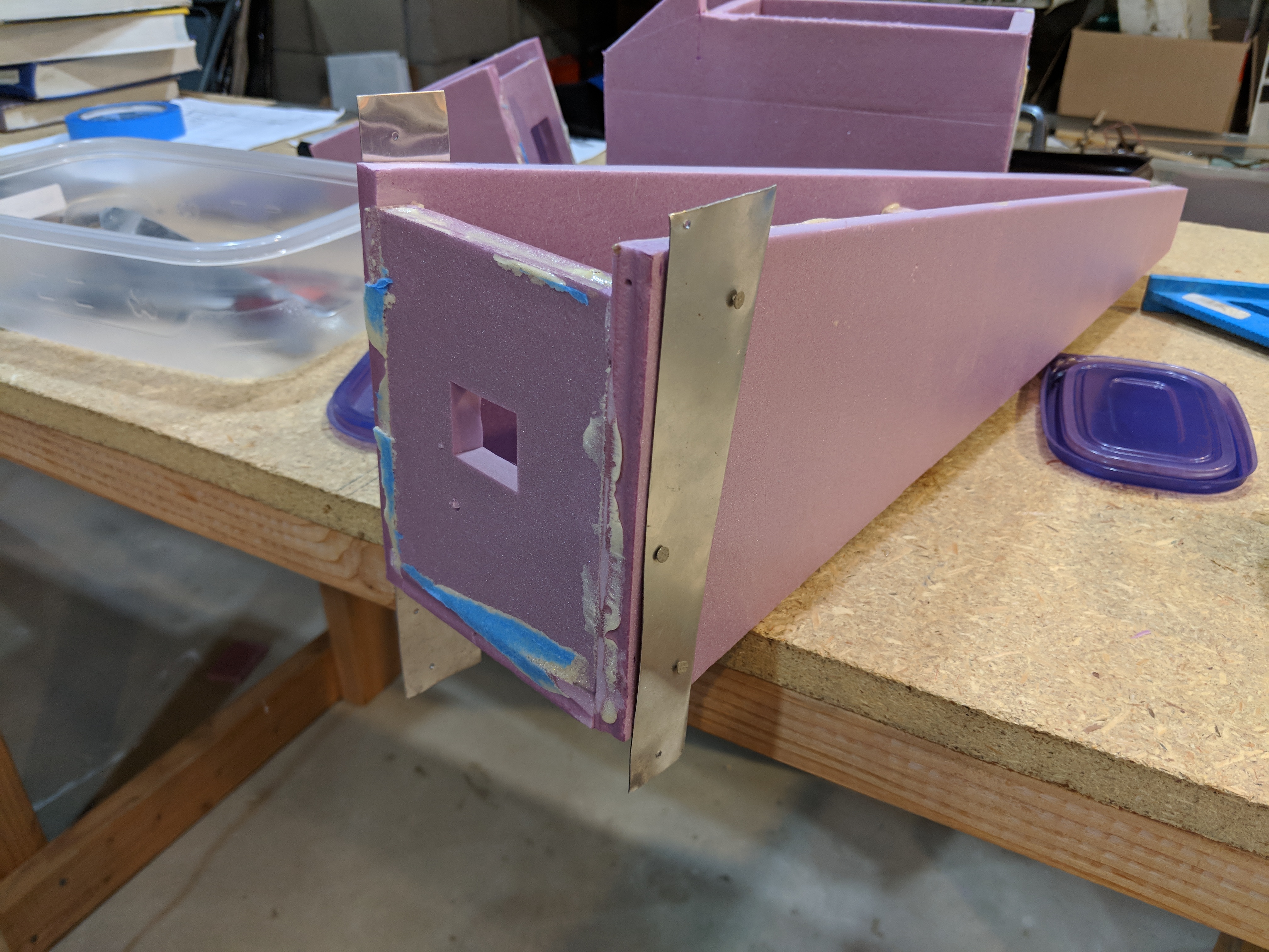
IMAGE #8: Templates added for slicing off end of tail section to make smooth for joining with cockpit section.
In image 8, you can see that before gluing the sections together, I used my hot wire cutter and some templates to slice the front and back of each section to make a smooth, clean cut.
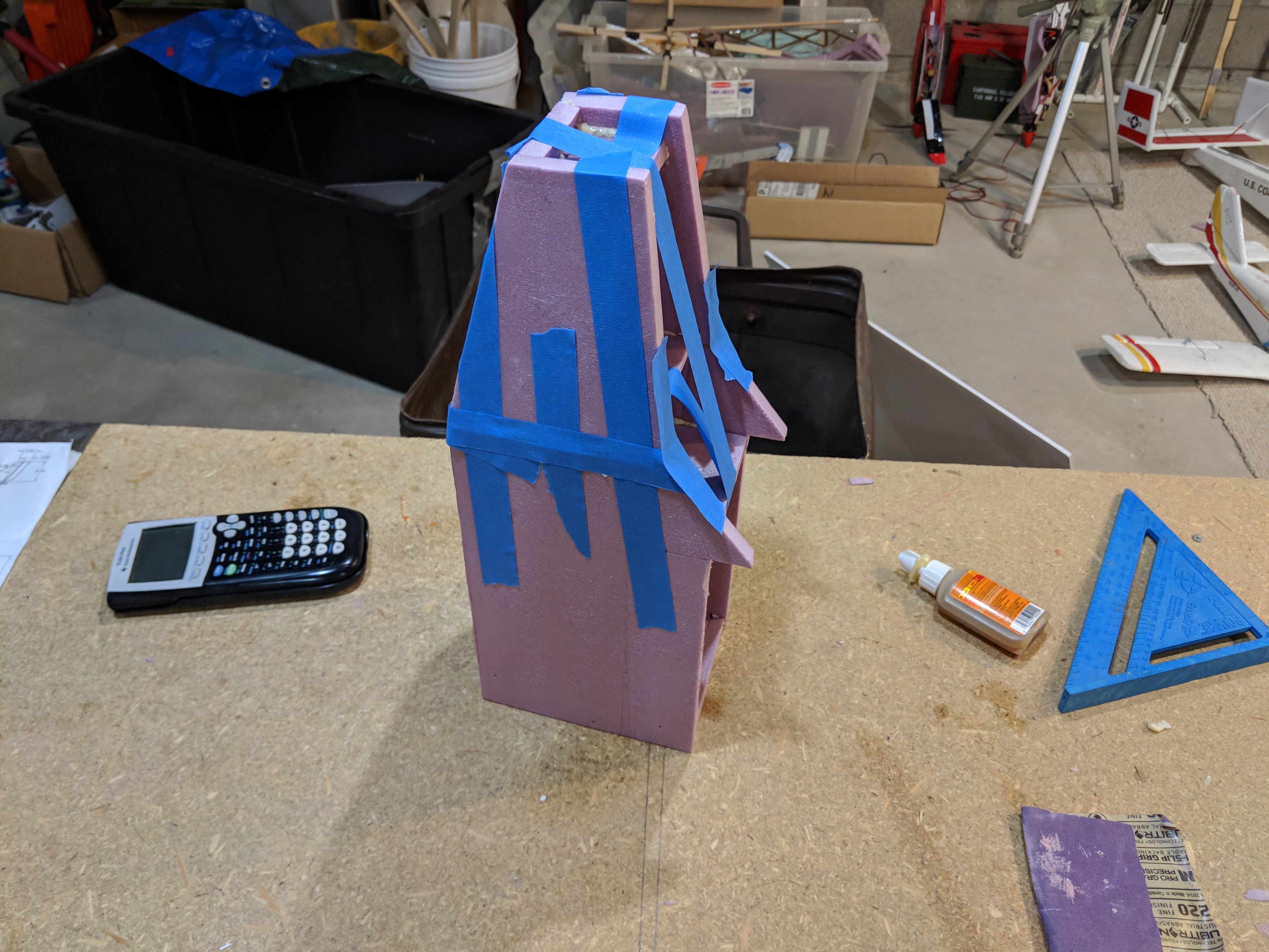
IMAGE #9: Nose, and cockpit sections being glued together.
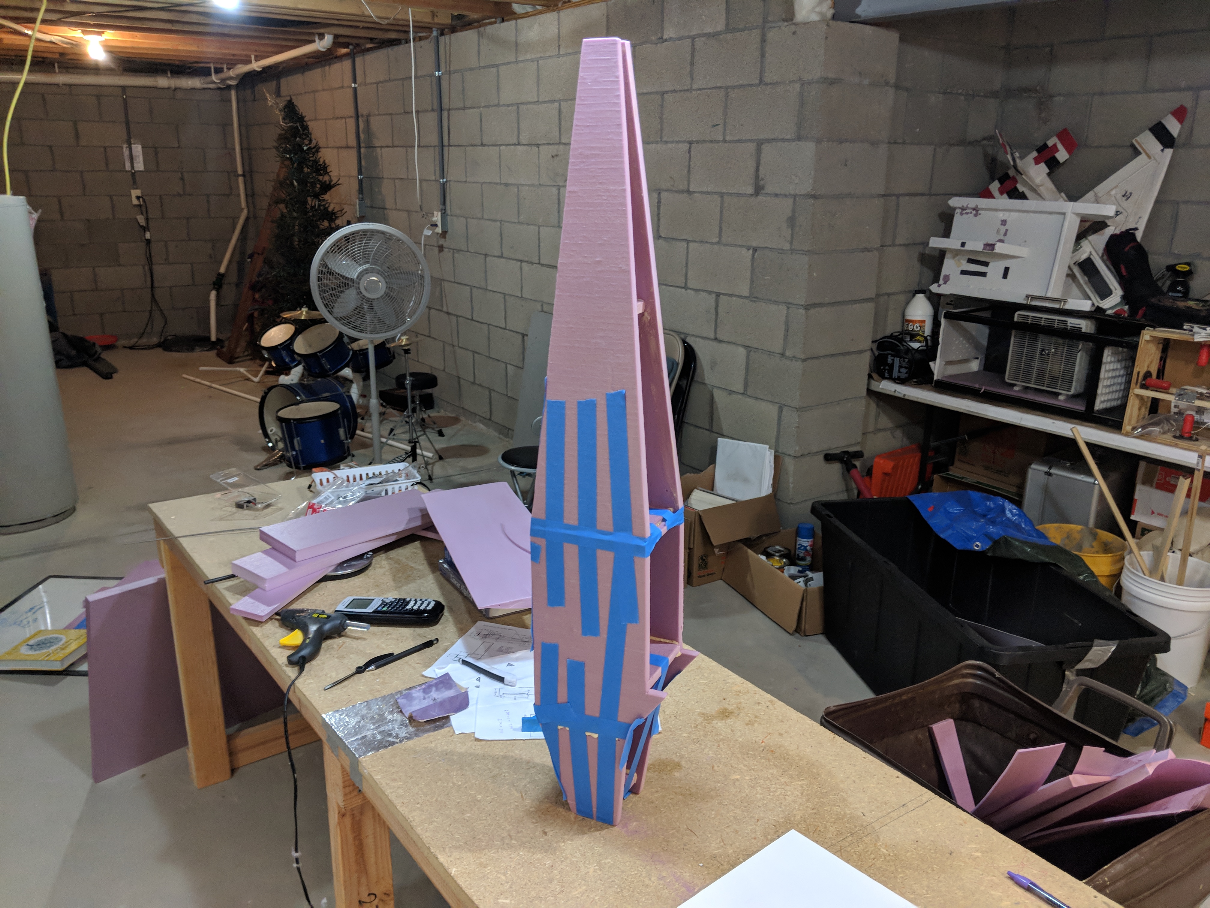
IMAGE #10: All 3 fuselage pieces being glued together, held in place with masking tape.
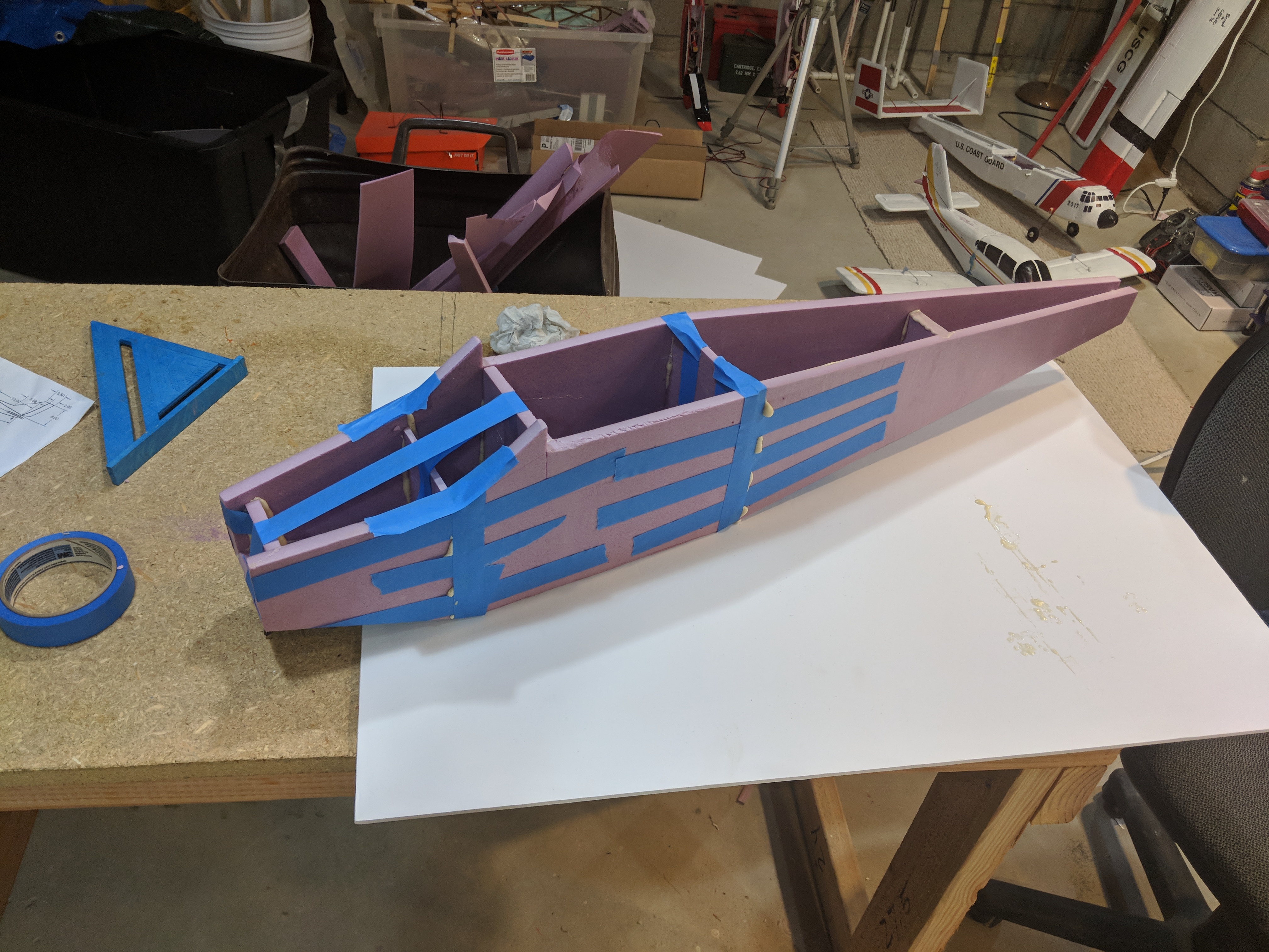
IMAGE #11: Fuselage.
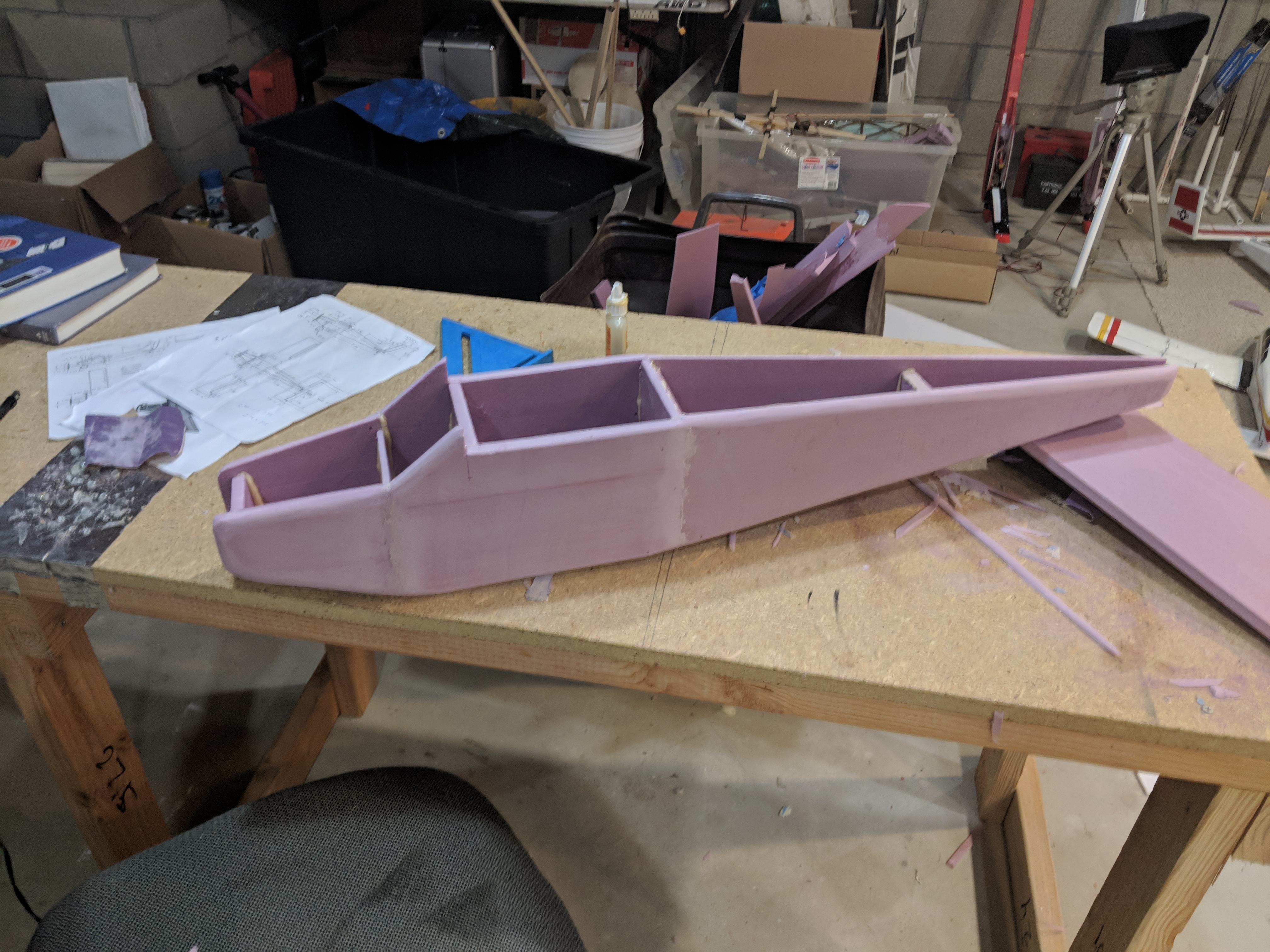
IMAGE #12: Sanded fuselage.
After the sections were all glued together, and the excess gorilla glue was cut away, I used a sanding block to sand the plane and blend the 3 sections together.
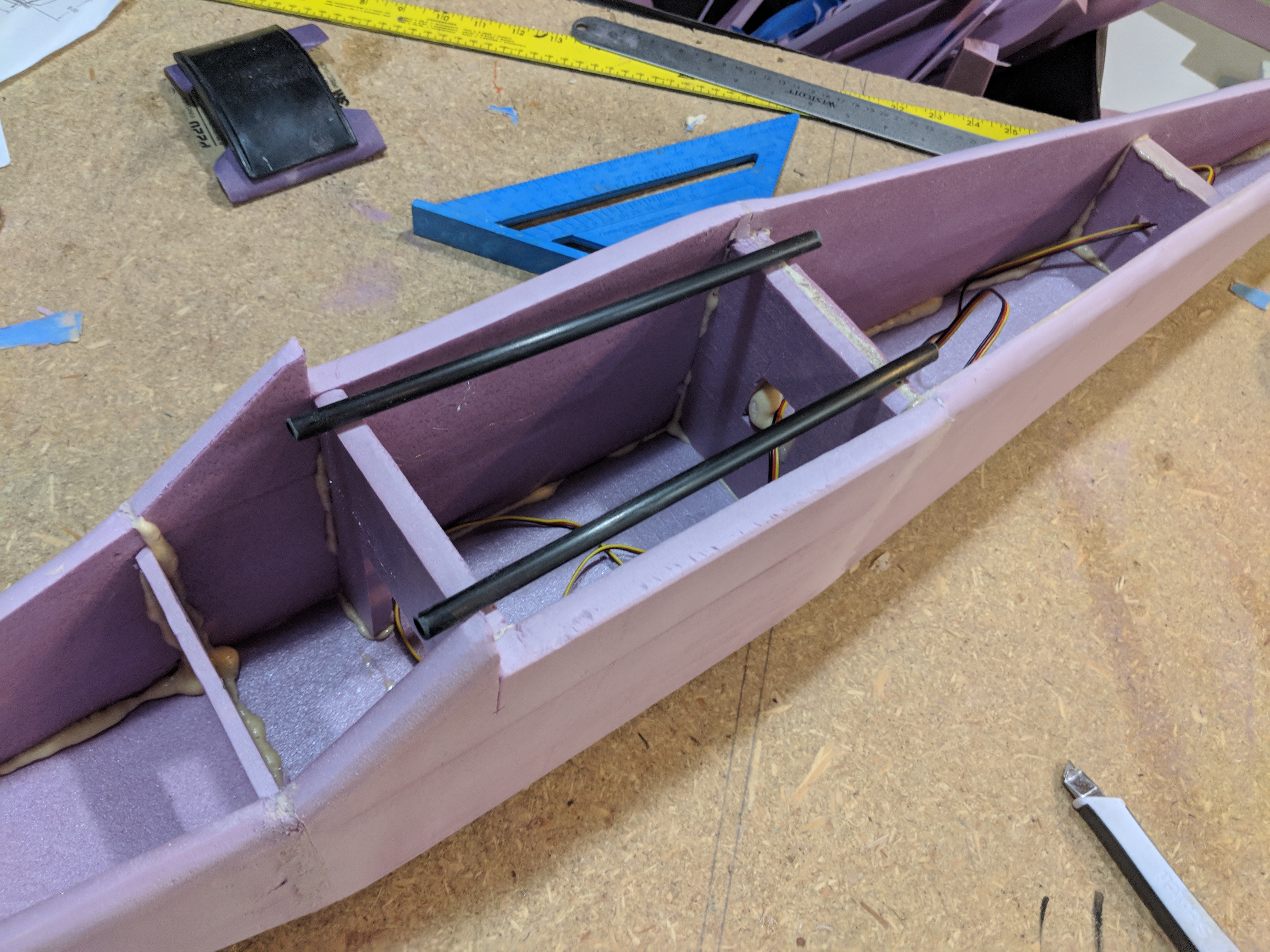
IMAGE 13: Preparing carbon fiber rods which will hold the rubber bands.
I used 2 carbon fiber tubes in the fuselage as anchor points for the rubber bands which will hold the wing onto the fuselage. These were gorilla glued through 2 of the formers within the fuselage.
2.) Wing Build:
Next, I built the wing. The wing is made of 3 pieces of foam. The center piece which is 5in wide which will go over the fuselage, and the 2 wing halves which are 24in wide. I used fusion360 to design an airfoil template which I then 3D printed. The airfoil is a standard 2412 "Clark Y" flat bottom airfoil. Since the PLA plastic used in 3D printing will melt from the hot wire cutter, I covered it in aluminum tape. I then used nails to hold the templates on each side of the foam blocks, and used the hot wire cutter to cut out the airfoil shape for the wing. Once the airfoils were cut out, I used gorilla glue to glue the 3 sections together. While it was drying, I placed some heavy weights on the center section, and propped up the wingtips to give it some dihedral. Once the glue was dry, I cut off the remaining and used a sanding block to sand it down.
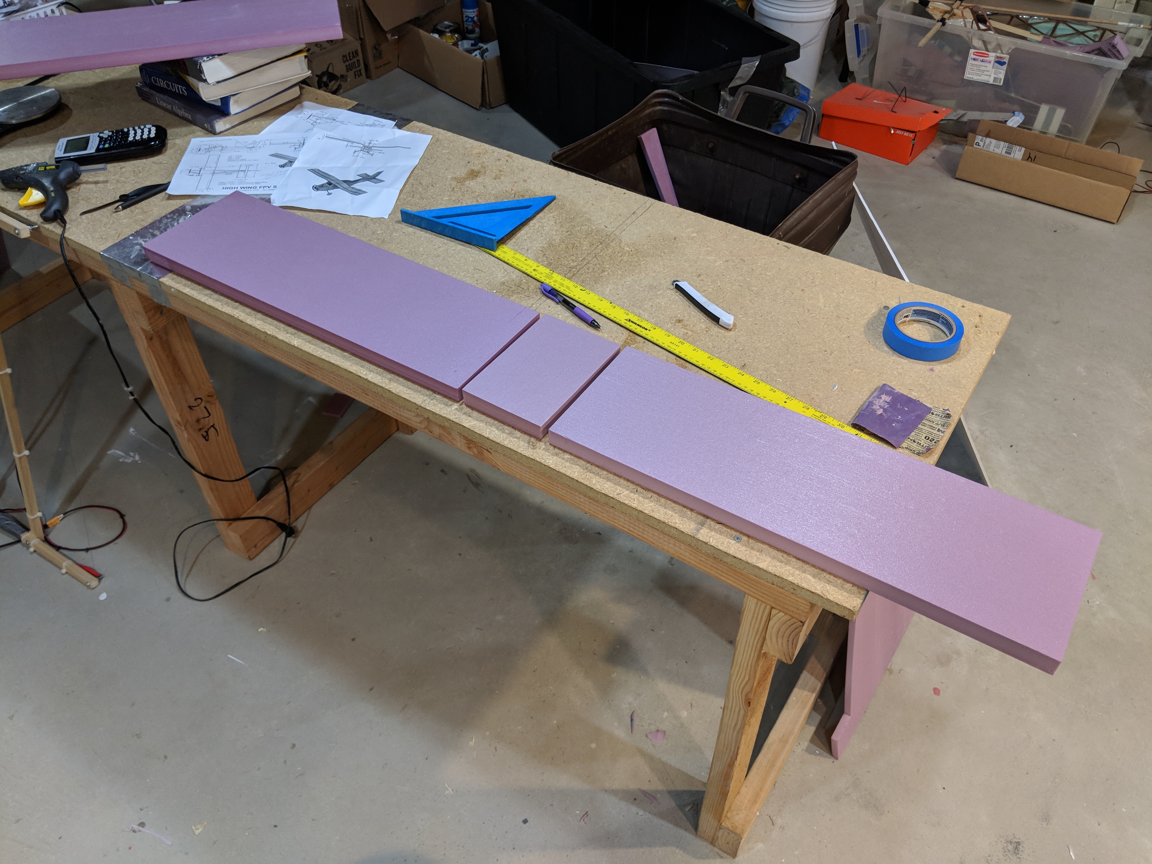
IMAGE 14: Three wing pieces.
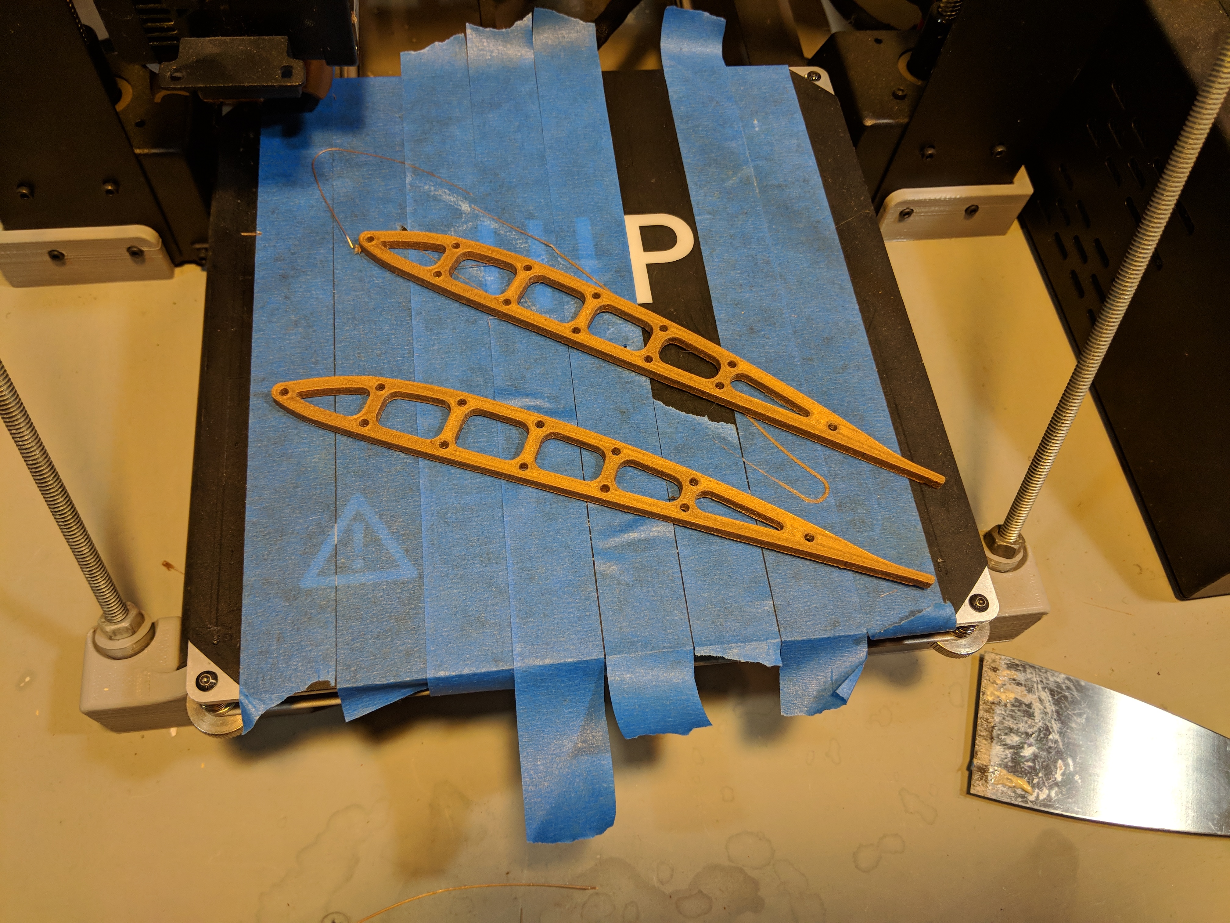
IMAGE 15: 3D Printed airfoil templates.
 IMAGE 16: Sanded Wing on Fuselage.
3.) Horizontal & Vertical Stabilizers Build:
I used a remaining 1/2 inch thick piece of foam for the stabilizers. I cut out the shapes and sanded the edges and corners down. A 1x6mm carbon fiber strip was glued into each stabilizer to give extra strength. After that, I cut out the elevator and rudder, before gluing the stabilizers to the fuselage.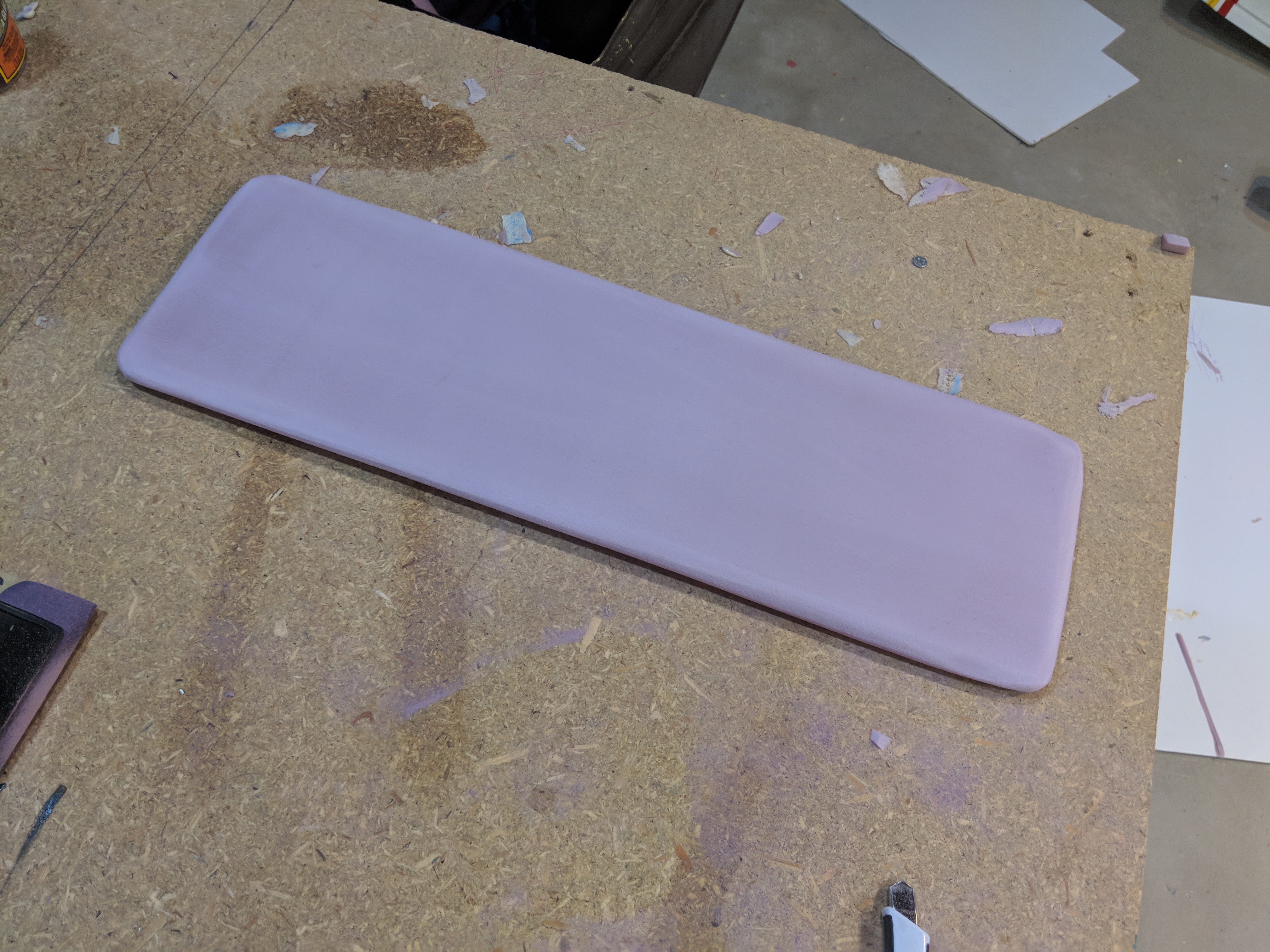
IMAGE 17: Horizontal stabilizer after sanding.
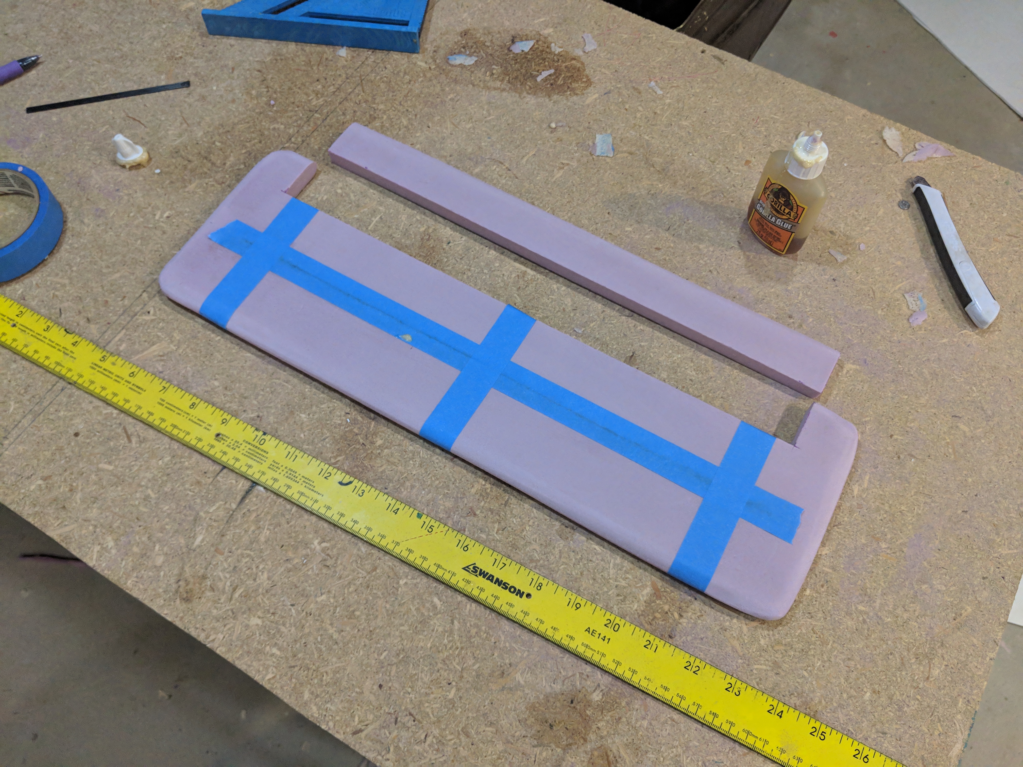
IMAGE 18: Elevator cut out of horizontal stabilizer.
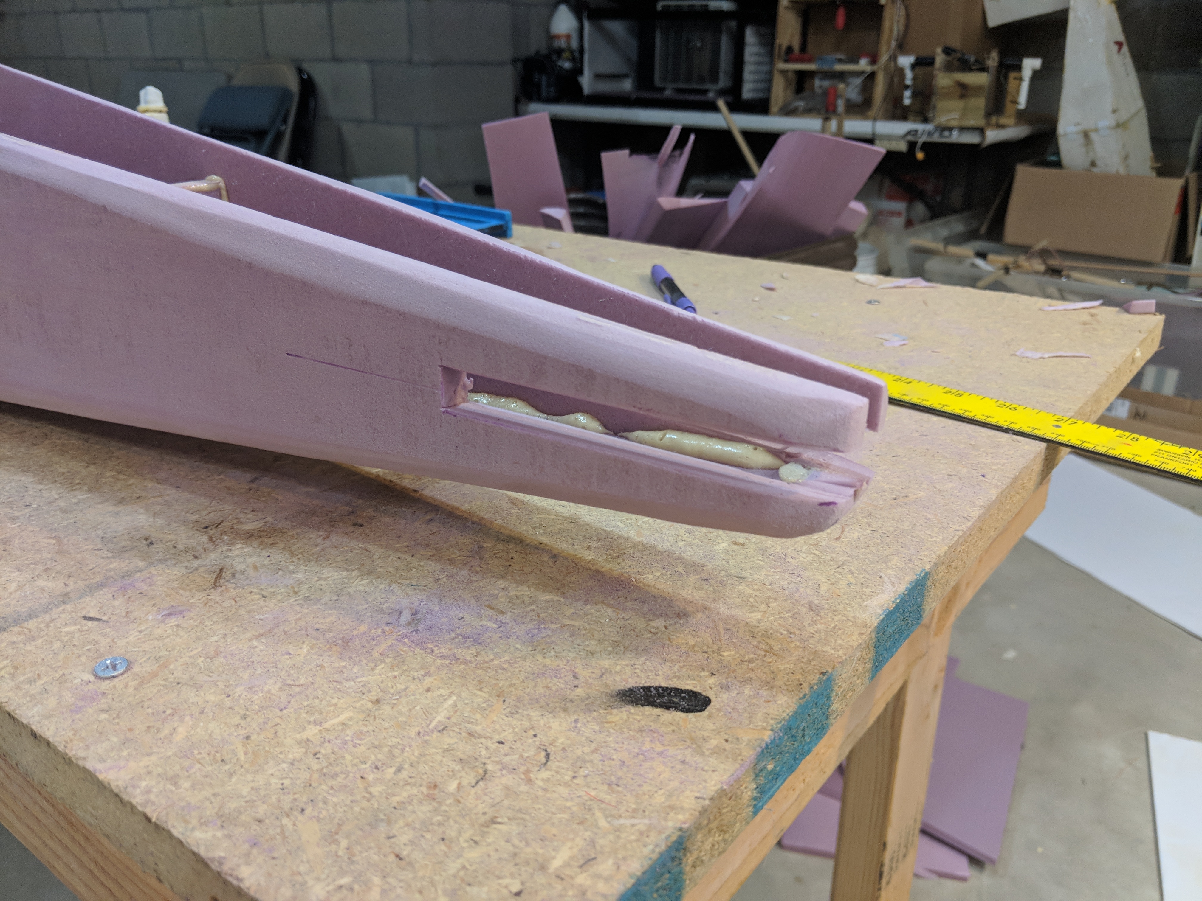
IMAGE 19: Slot cut out of rear fuselage for the horizontal stabilizer.
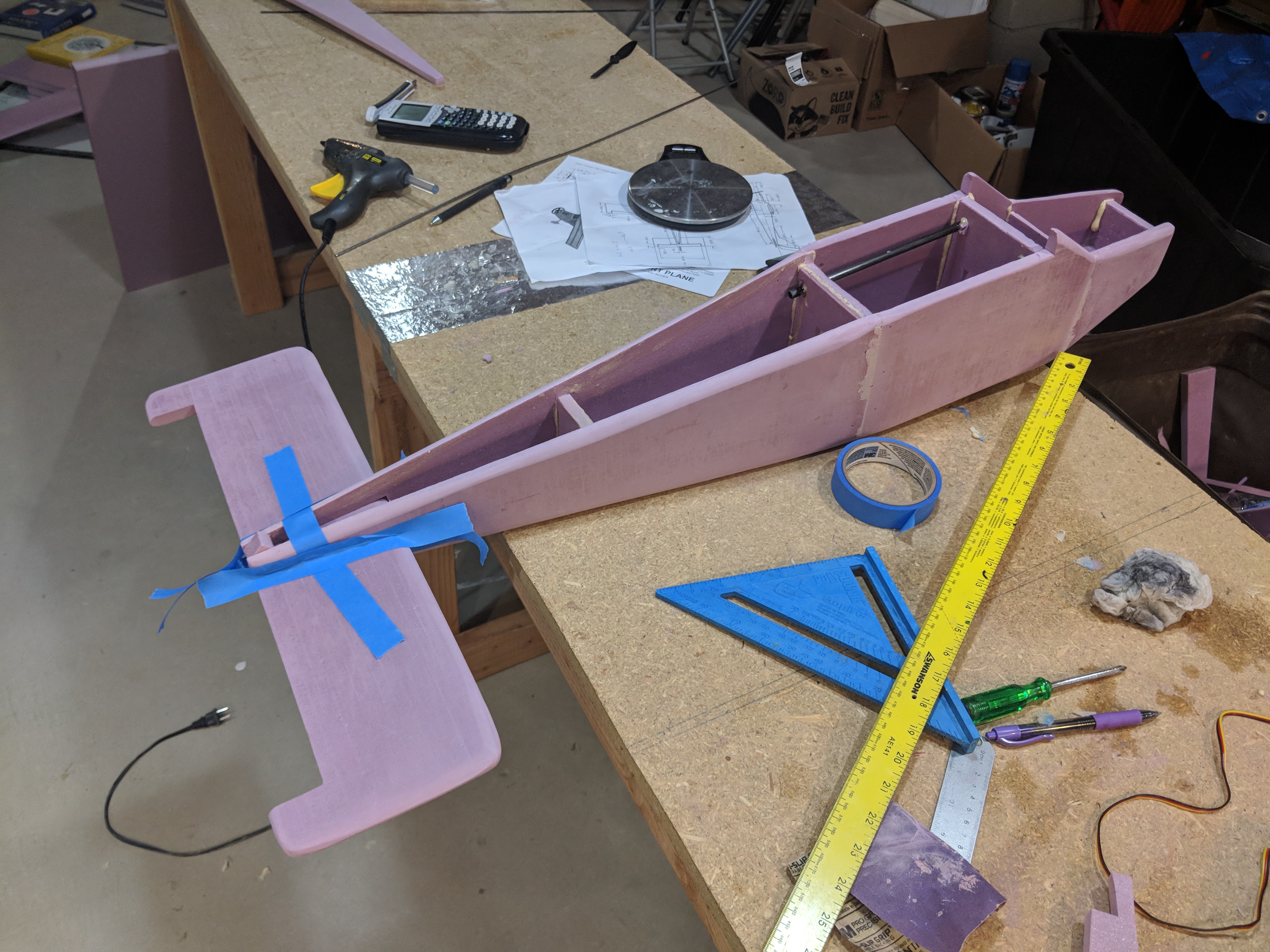
IMAGE 20: Horizontal Stabilizer gluing into fuselage.
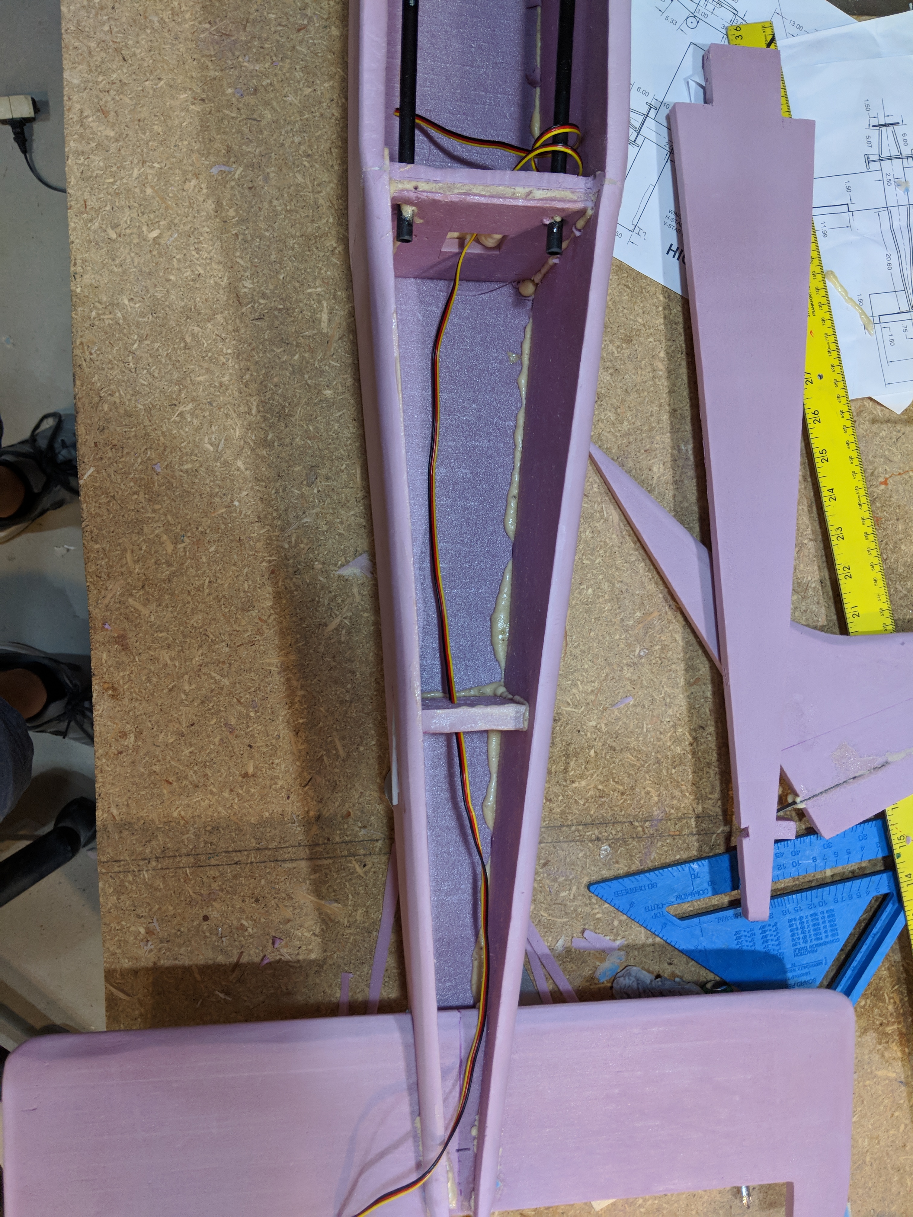
IMAGE 21: 3-wire Cable for FPV Camera to be mounted on the vertical stabilizer.
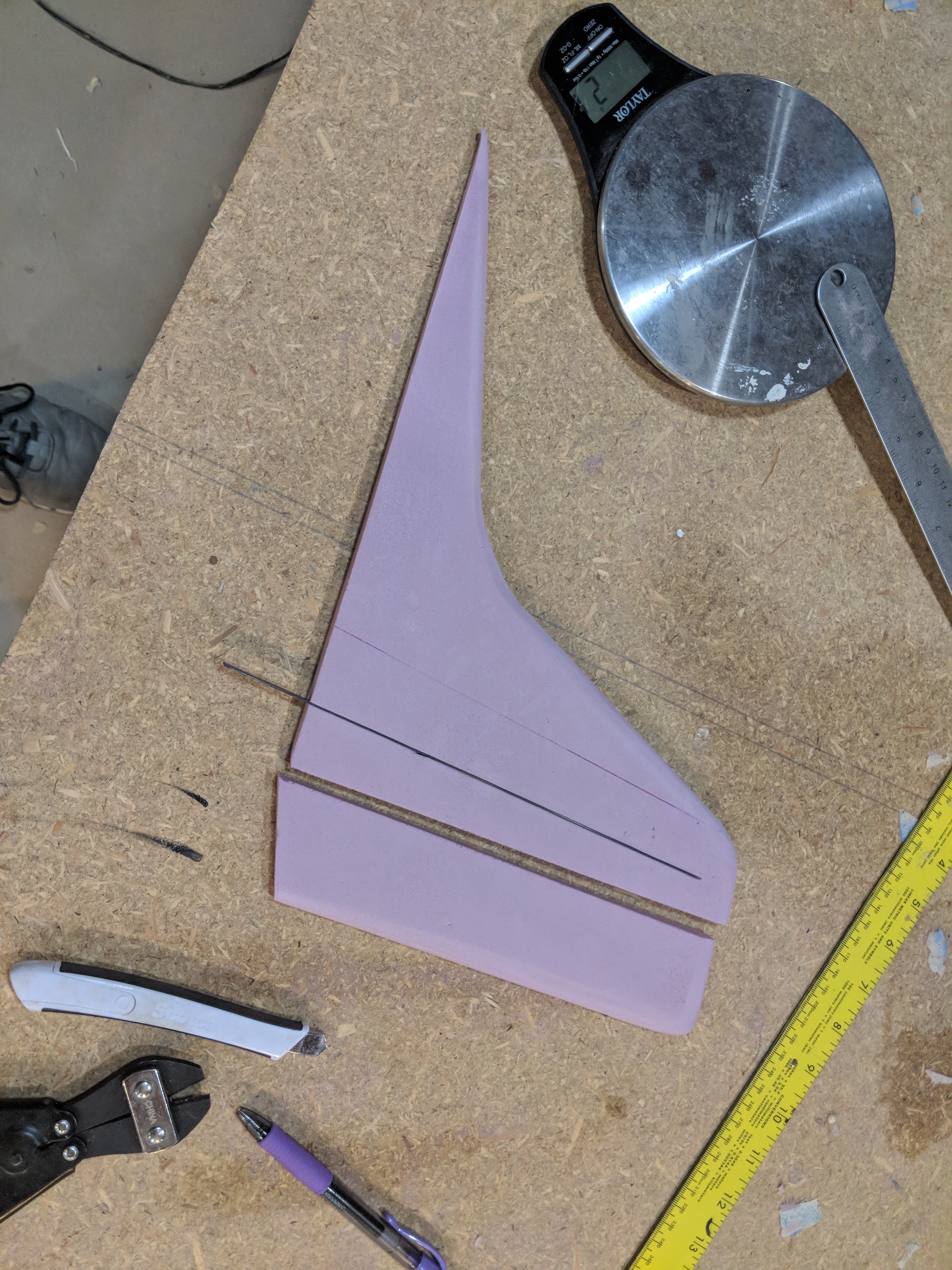
IMAGE 22: Vertical stabilizer with carbon fiber strip installed.
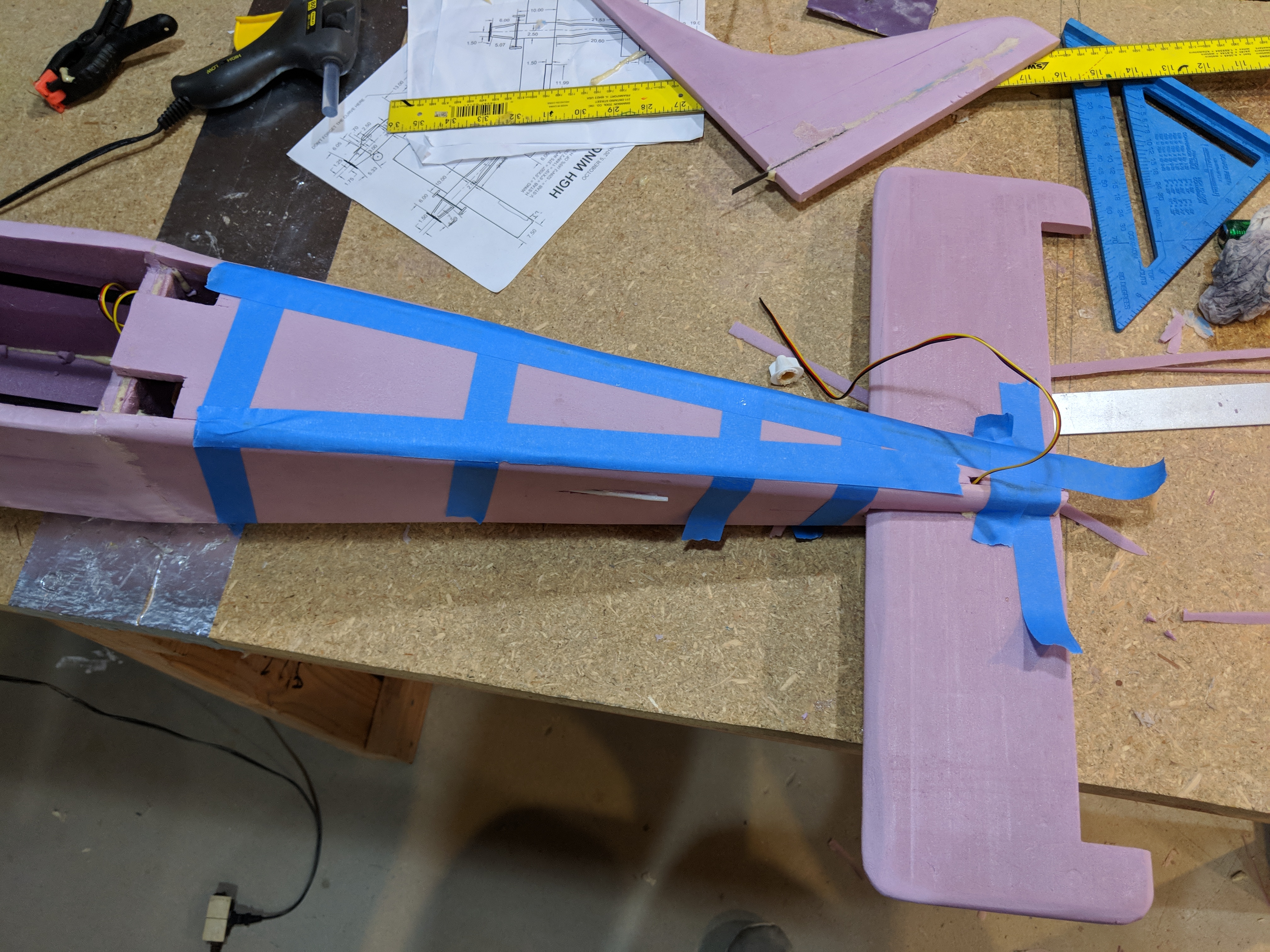
IMAGE 23: Rear fuselage top piece glued in.

IMAGE 24: Vertical Stabilizer glued into fuselage.
4.) Motor Mount:
Next, I made the motor mount. I used a small piece of plywood and gorilla glued it onto the firewall on the nose of the plane. I used a clamp to hold it down while the glue dried.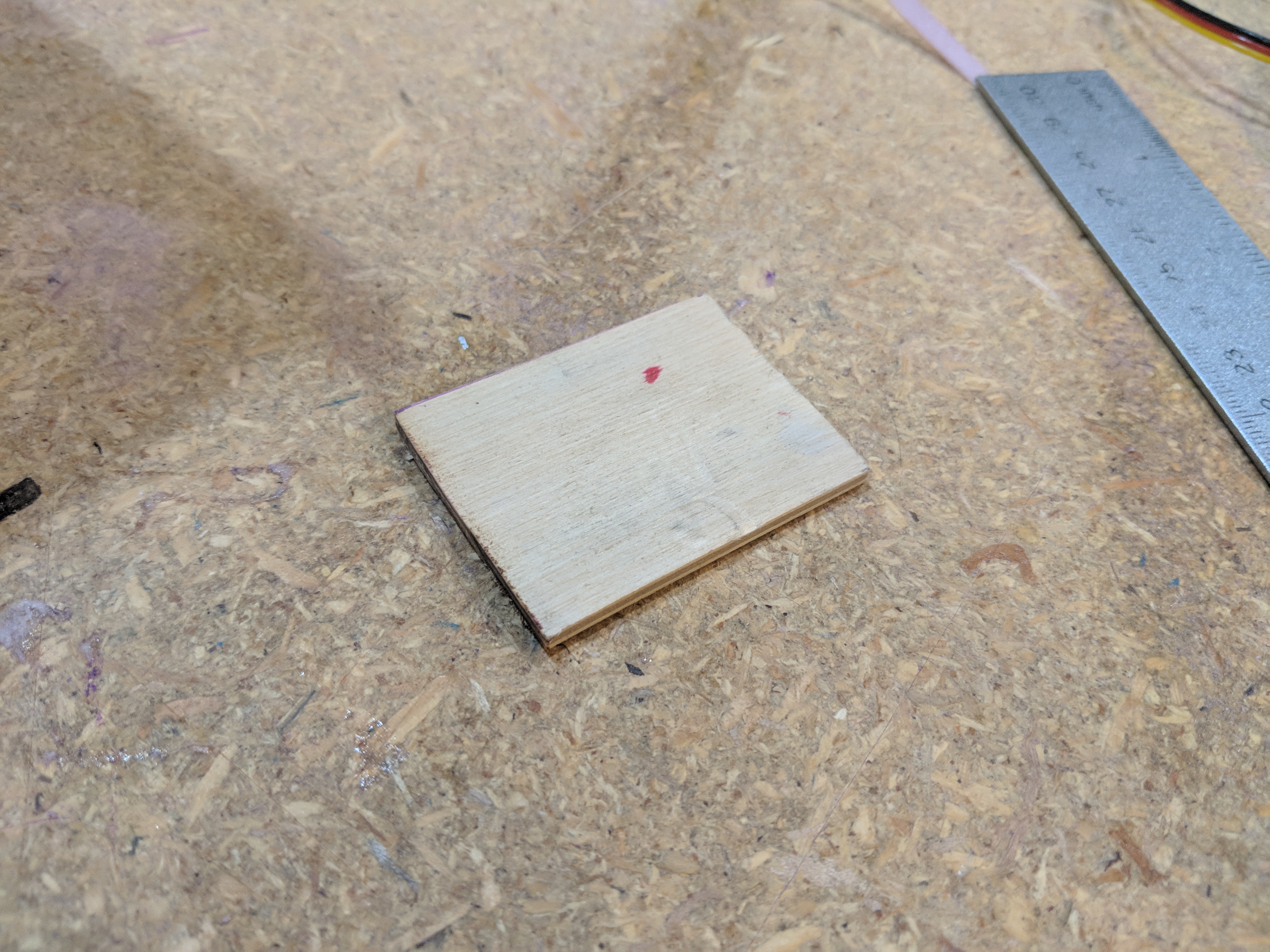
IMAGE 25: Plywood motor mount.
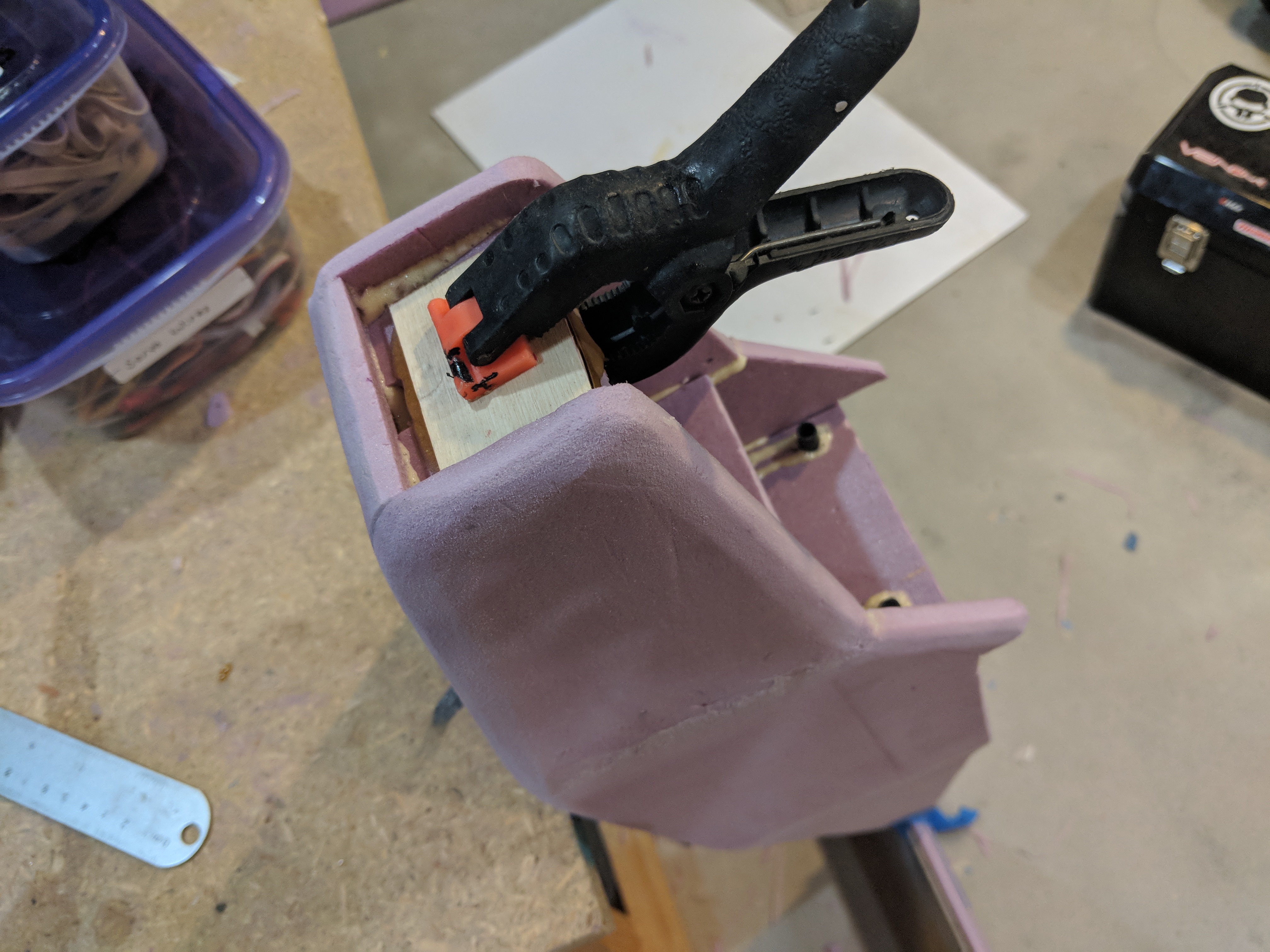
IMAGE 26: Motor mount glued onto firewall.
5.) Landing Gear:
The landing gear would be a taildragger, with 2 large bush wheels at the front of the fuselage. The landing gear wire would be bent with a long protrusion which would be slid into the 3d printed bracket shown below. The landing gear wire was then glued into the 3D printed bracket. This bracket was glued into a hole in the fuselage.
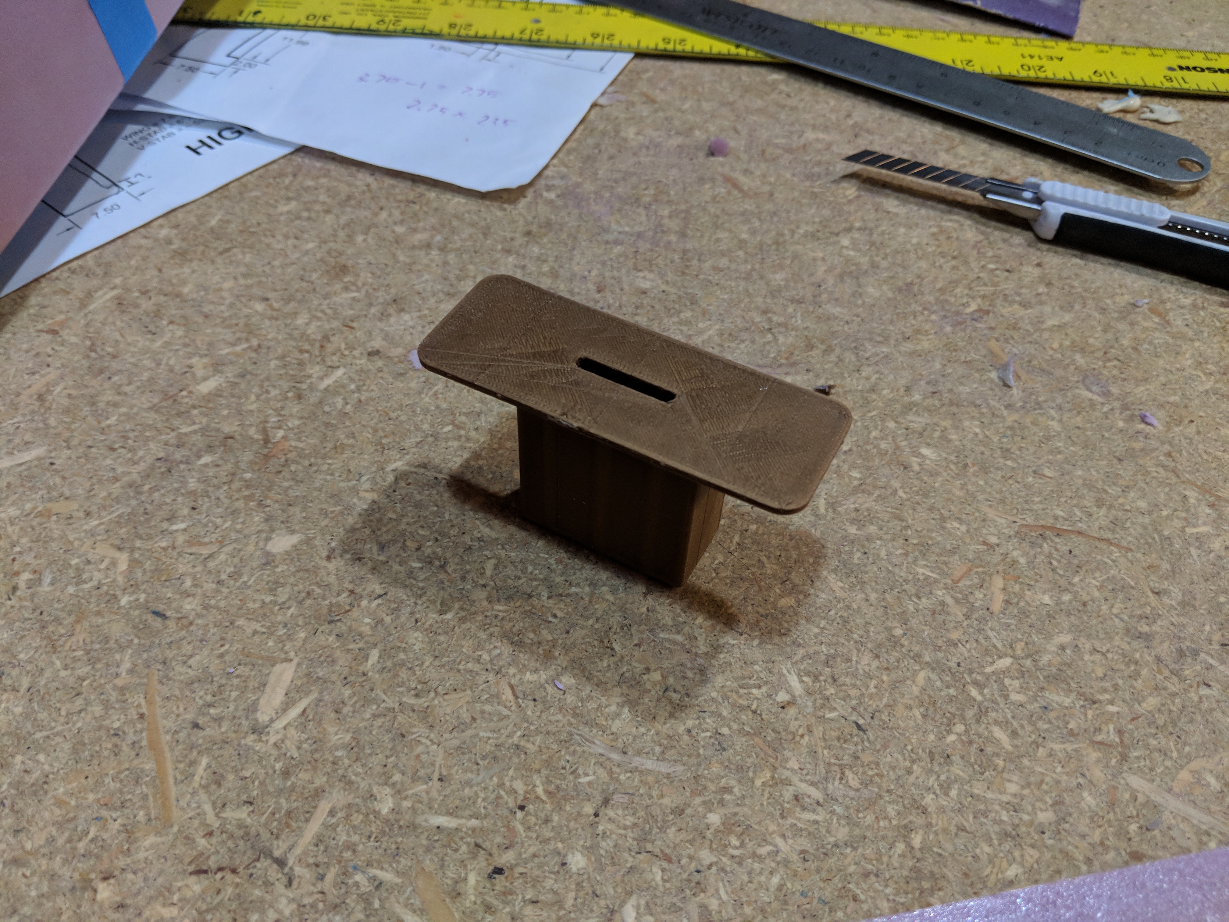
IMAGE 27: 3D printed Main landing gear bracket.
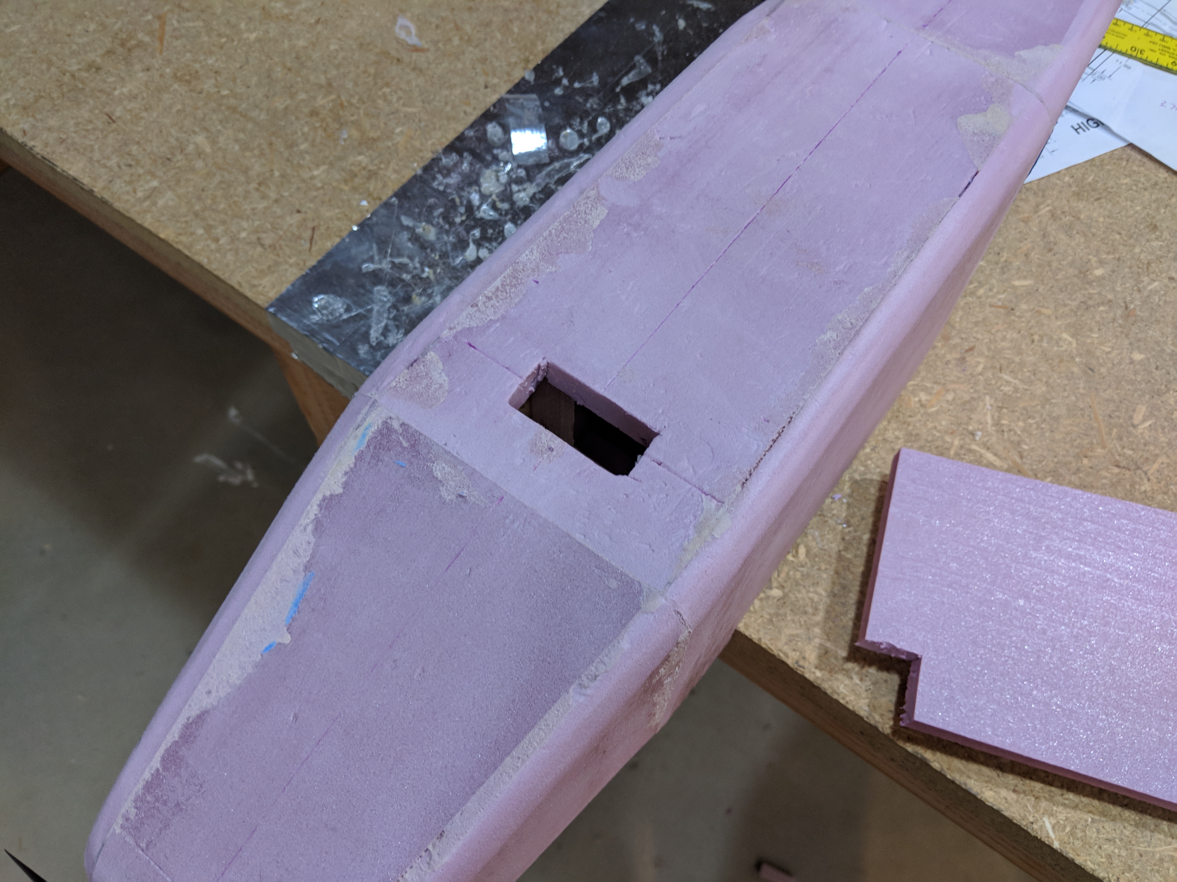
IMAGE 28: Hole in fuselage for main landing gear bracket to be glued into.
The tail skid is a piece of foam with a small 3D printed part which will prevent the foam from being destroyed from contacting the ground.
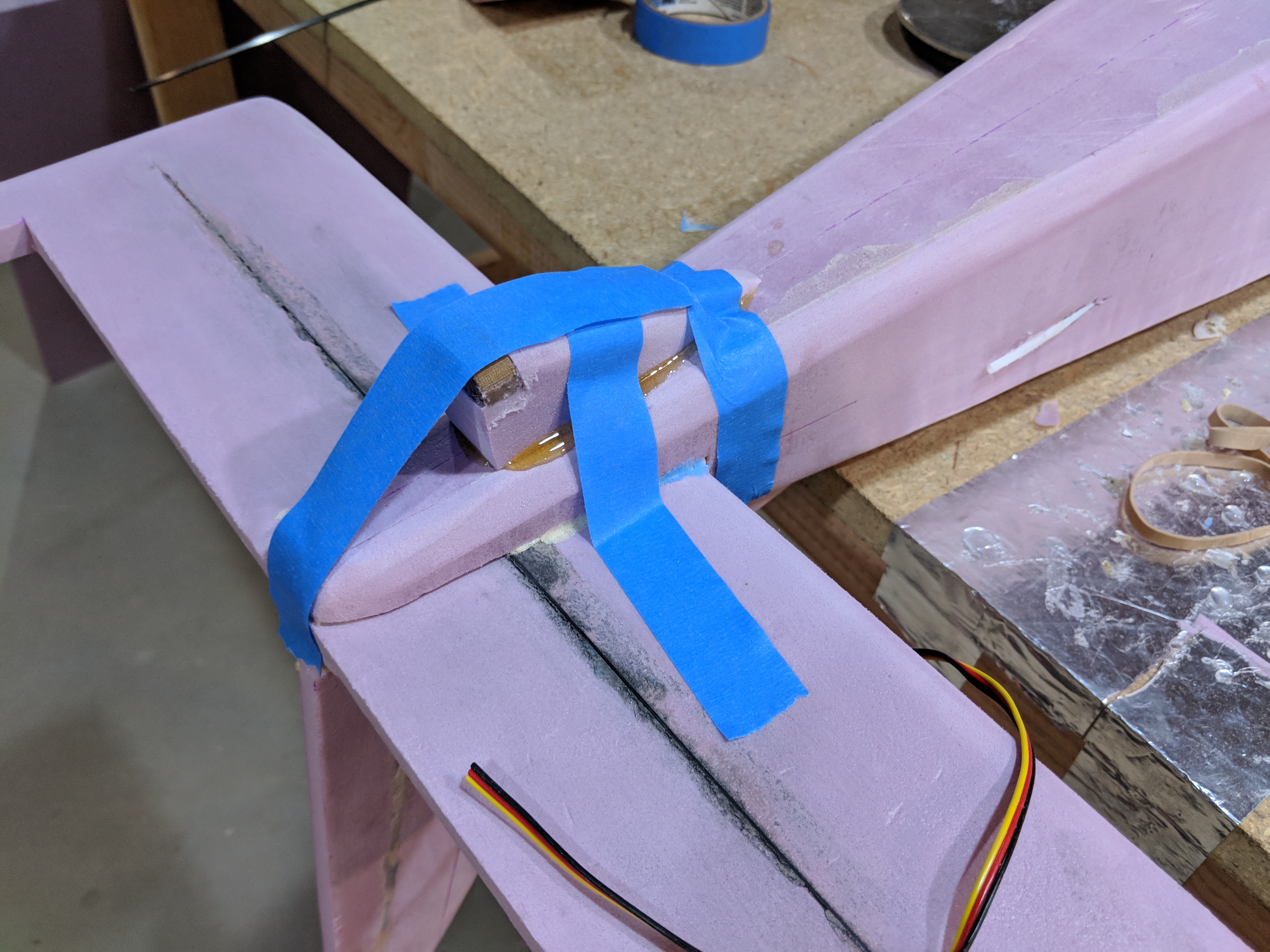
IMAGE 29: Tail skid with 3D printed part for contacting the ground.

IMAGE 30: landing gear installed with 3in bush tires.
The video below shows an update on the plane up to this point.
VIDEO 1: Update #1
7.) Paint:
Next, the plane was painted. I used standard Rustolium latex house paint along with a brush and several foam wedges to paint the colors on. I began with 3 layers of white over the entire plane, then added the red and yellow accents to the wings and fuselage. The cockpit windows were freehand drawn with a sharpie permanent marker. I 3D printed a thin template for the N-number which i used a marker to draw on the rear portion of the fuselage.

IMAGE 31: Fuselage with white coat of paint.
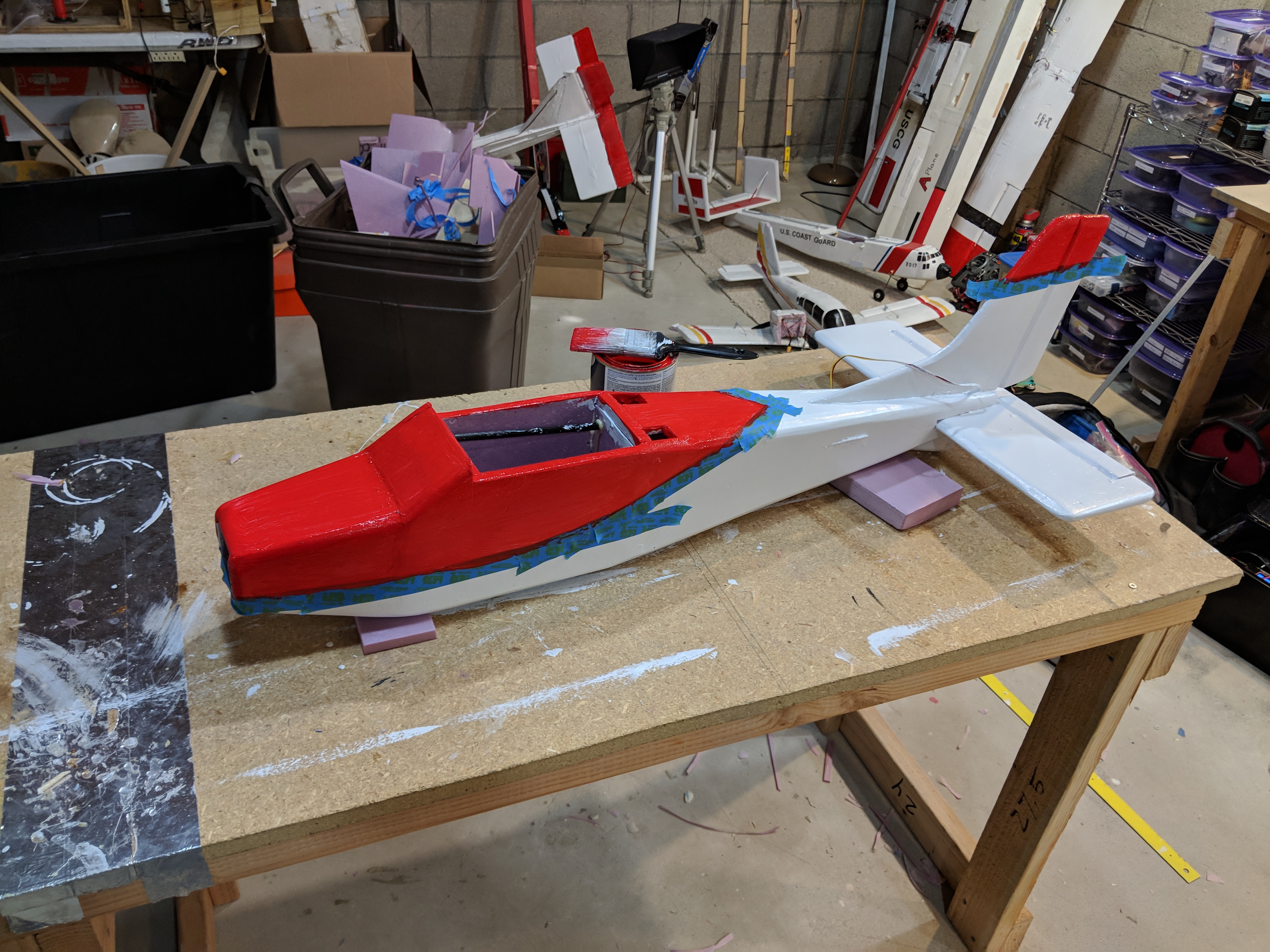
IMAGE 32: Fuselage with read accent around nose, cockpit, and tail.
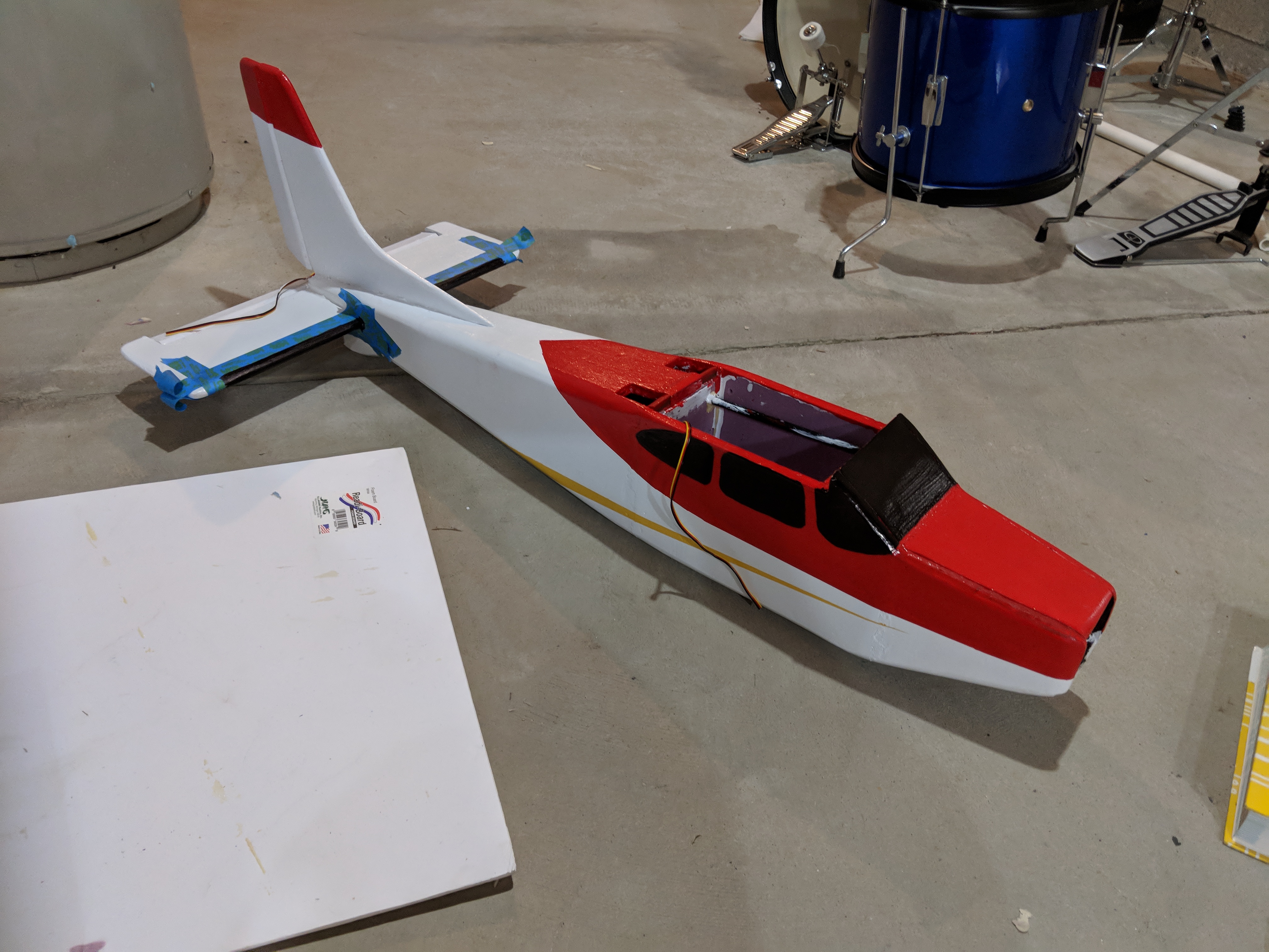
IMAGE 33: Fuselage with cockpit windows drawn on and yellow accent.
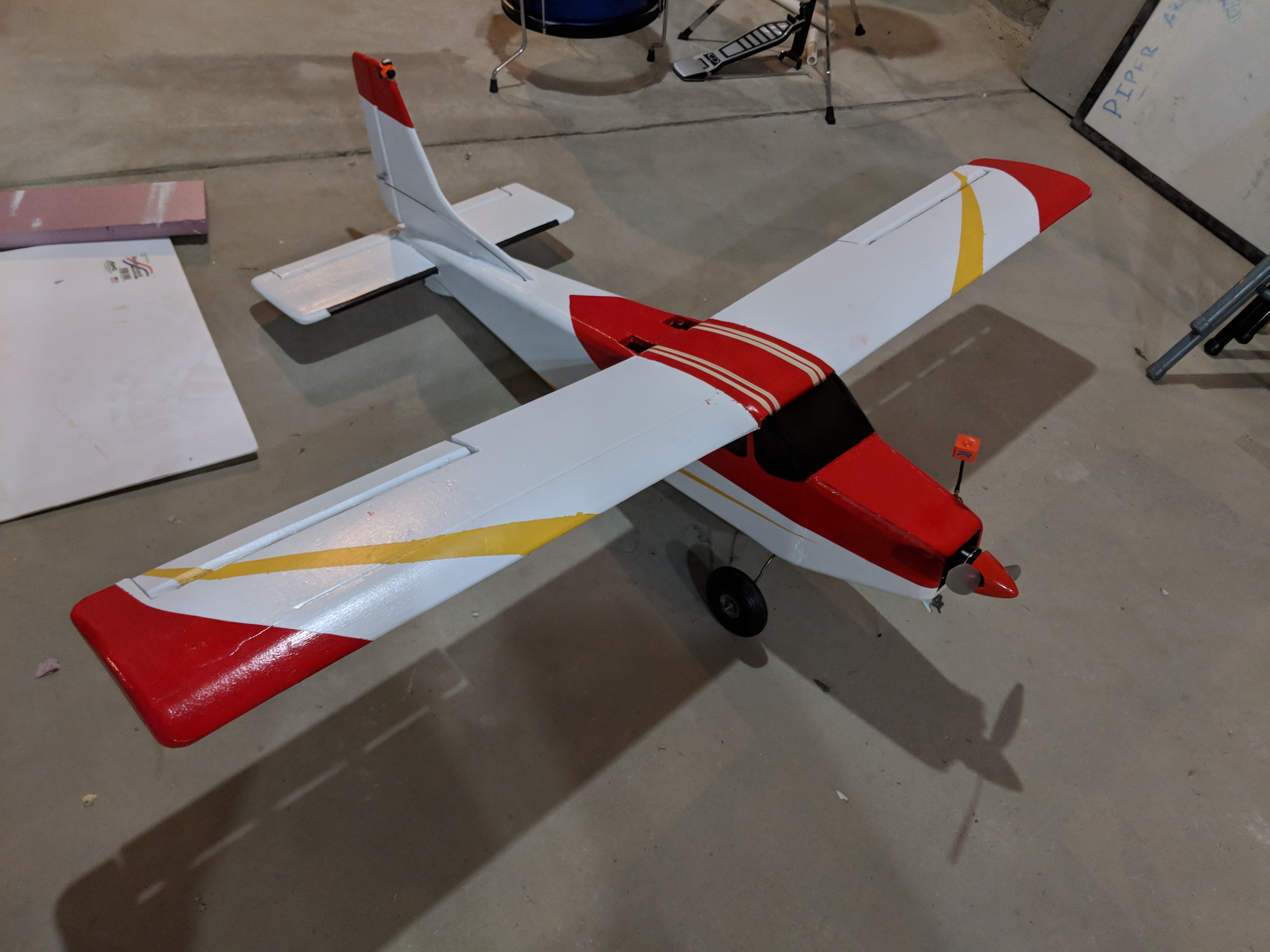
IMAGE 34: Completed paint scheme.
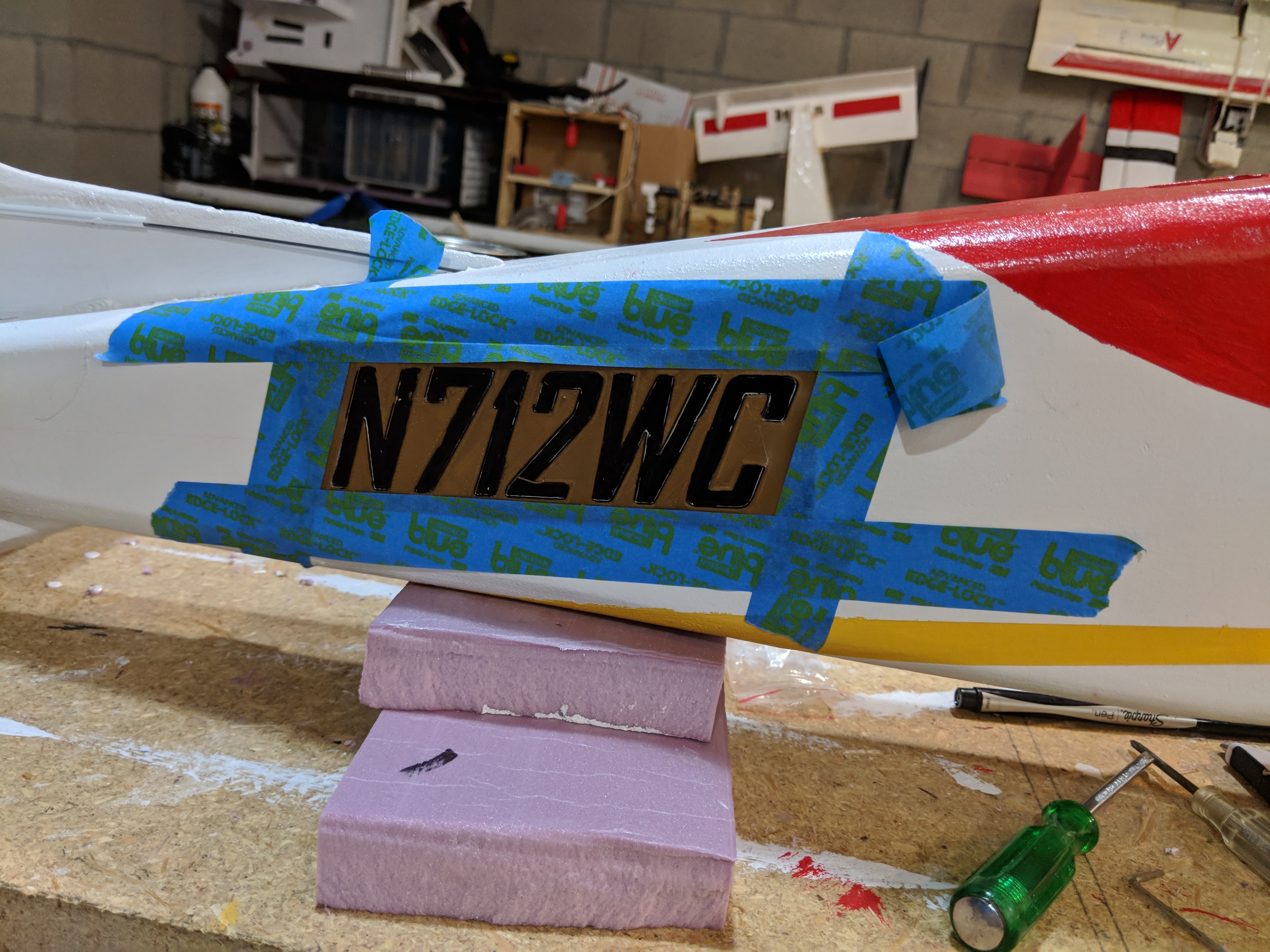
IMAGE 35: N-number template used to paint on number to fuselage.
6.) Adding Electronics:
This video below best explains the electronics used in the plane.
VIDEO 2: Update #2
The plane is powered by a 4s lipo battery. The ESC has a built in BEC which steps the battery voltage down to 5v. This 5v supply is used to power the 4 servos. An additional Polulu 5v converter is used to power the VTX, camera, and DVR. A Runcam micro Swift 3 is glued into the tail, and connects to a readymaderc vtx, and a Eachine DVR for recording the clean video. I also added a switch which can be used to turn off the entire FPV system if it is not needed for a flight. Below is a list of all electronics used.
Motor: Emax 3506 650kv motor w/ 11x4.7 prop.
ESC: Turnigy 40A plush
RX: Frsky S6R
Servos: Emax ES08MAII, and ES08II
VTX: RMRC Nano Cricket w/ Strix hoot circular polarized antenna
Camera: Runcam Micro Swift 3
DVR: Eachine Pro DVR
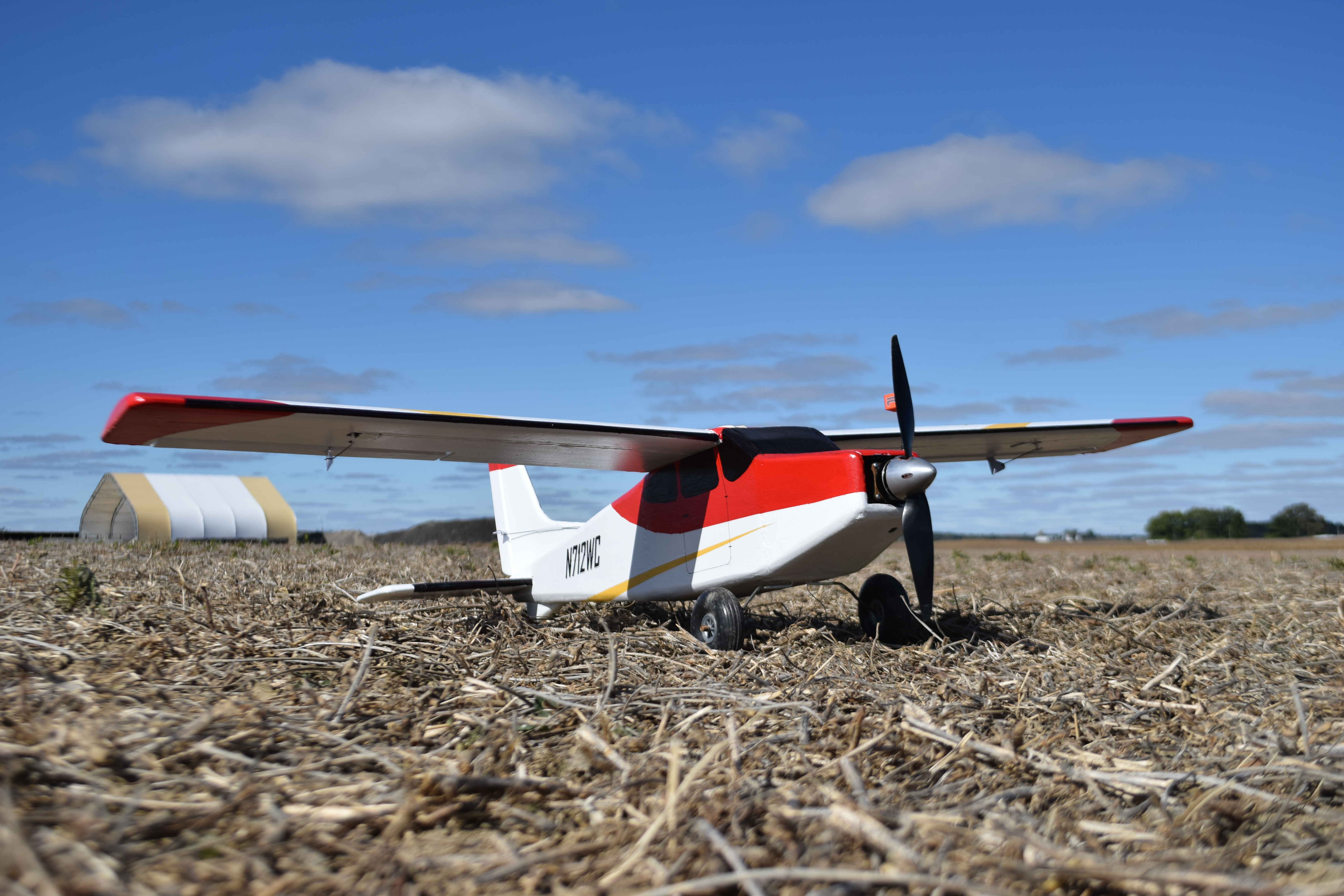
7.) Finished Plane:
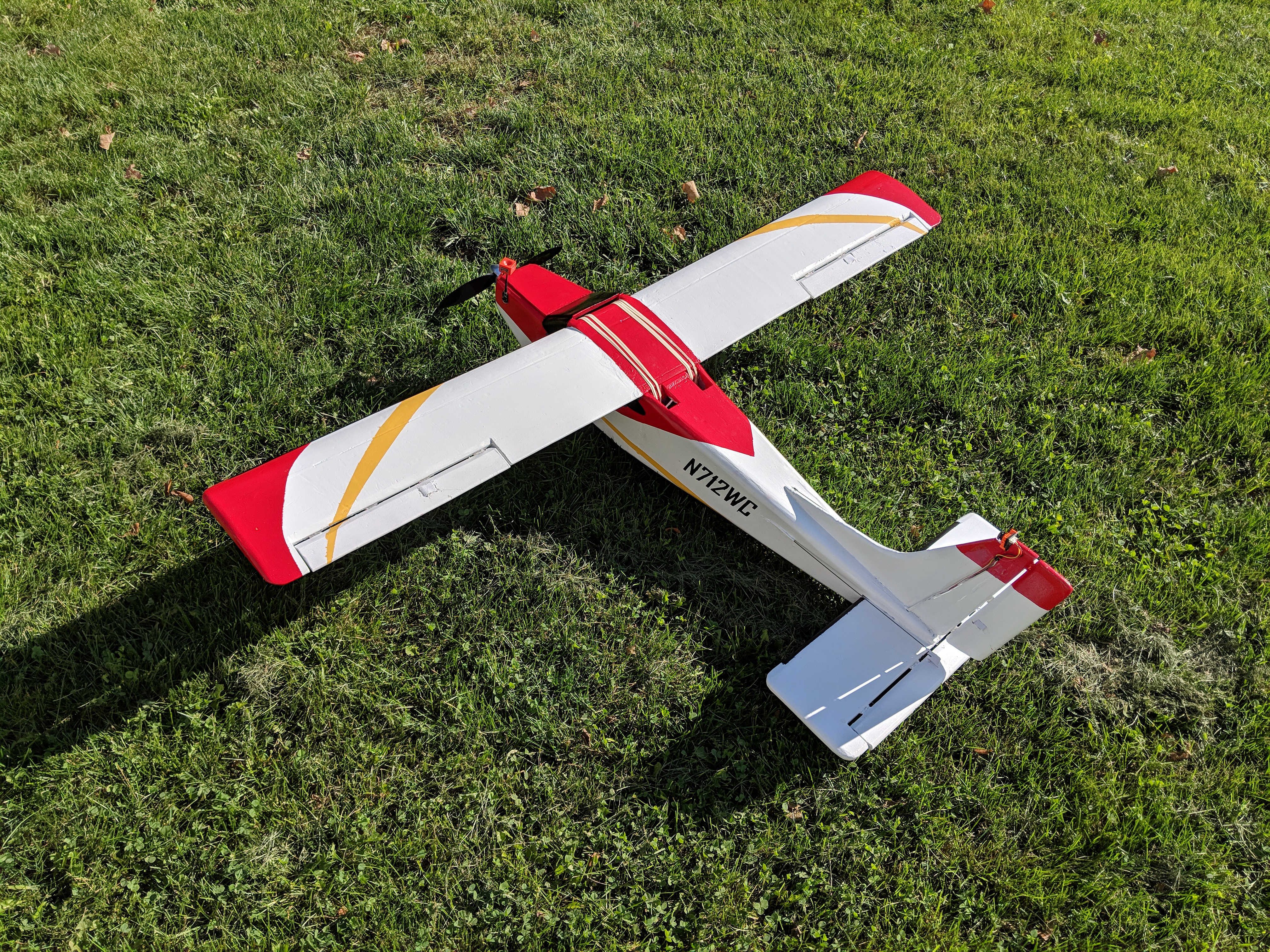
Here are some pictures of the finished plane.


8.) Maiden Flight:
Now it was time to do the maiden flight. Check out the video below to see how it went.
VIDEO 3: Maiden Flight
The plane flew well, but needed some up trim. I ended up moving the CG back which made it fly better. The gyro stabilization within the receiver worked very well to eliminate the plane from rocking around due to the wind. I was also able to get some aerial footage of the plane from my friends quadcopter. That video is shown below:
VIDEO 4: Air to Air Video of the plane.
And the next video does a good job showcasing the plane taking off and landing.
9.) New Wing with Flaps:
Ever since the maiden flight, I knew I needed to build a larger wing with flaps. This new wing has the same chord, but is 4 inches longer, has flaps, and wider ailerons. The plane with the original wing wasn't quite responsive enough on the roll as I'd like, so that is why the new ailerons were larger. The video below shows the new wing, along with my first full FPV flights with the plane using my FatShark Goggles.
VIDEO 6: New Wing, and FPV Flights.
10.) Conclusion:
This plane is by far the best plane I've built so far. It utilized new build techniques and is also very ascetically pleasing to me. The plane flies very well, with no bad tendencies to tip stall, or spin, and can land reliably on rough terrain without fear of damaged landing gear. The rugged tires give it the ability to takeoff and land, some of the most fun part of flying planes, and allows a full FPV flight to be conducted from takeoff to landing which gives a great immersive experience. Overall, this is my favorite plane I have built.
Thanks for reading this article, and watching the videos. I hope you enjoyed the build and maybe even learned something new. If you have any questions or comments, please leave them below and I will respond as quick as possible.
-Brock


Log In to reply
Log In to reply
Log In to reply
Log In to reply
Log In to reply
Awesome job!
Rob
Log In to reply
Log In to reply
Log In to reply
Log In to reply
Log In to reply