
__________________________________________________________________________
Balanced Pusher Wing

Free plans to move the motor of your Versa Wing pusher forward to balance without added weight or “batterying” up. This article will aslo show you how to fiberglass Readi-Board to make it uber strong.
by: HilldaFlyer February 2015
Admittedly, I have now built and destroyed a few FT Versa Wings. The first Versa Wing I built was the tractor style. Very simple build, pretty easy to fly, but I have to add that got pretty frustrated because I would break the prop almost every single time I landed or gently crashed.
Balancing the Wing
The pusher style Versa Wing seemed like the cool way to go in order to protect the propeller/motor from nose first impacts. Like the Versa Wing Tractor, the pusher style build was easy, however, like mentioned by others, I had the hardest time trying to get it balanced on the CG, even with mounting the battery completely on the front of the wing. In the build video (http://flitetest.com/articles/ft-versa-wing) Josh mentioned that when you convert to the pusher, you need add weight to the front by “battering up” or adding lead (weight). I really didn’t want to add dead weight or purchase a bigger battery just to balance my wing, so I thought about building a battery pod that would protrude out the front.
What are the alternatives? The two heaviest components on the plane that can be used to adjust the balance are the battery and motor. Since the battery was already in the front of the wing, best way to adjust the CG was to move the motor forward. That would necessitate cutting into the wing design. In order to determine where to place the motor to balance on the CG, I taped the battery and electronic components to a completed Versa Wing

and moved the motor forward until the balance was achieved. In the end, it turns out that I moved the motor forward about 8 cm to achieve the balance at the CG marks. Since my powertrain uses a 8” propeller, the width of the cutout would be 11 cm, which is 4.33 inches on either side of center. The notch was cut out and the motor mounted. I don’t have any pictures of the first two completed pusher wings, but they both flew great. The first one died after it had an argument with the landing strip which broke it in half. The second one died in a similar fashion as the pilot was attempting a low altitude terrain skimming fly by. Analysis of the broken remains indicated the notch cut out for the motor sufficiently weakened the trailing edge so that impacts to the nose would rip the foam board at the motor cutout. Since the redesigned pusher wing flew so well, without added weight, I decided to make another, but I wanted it to reinforce the structure so that it would survive a simple nose crash. I decided to fiberglass the wing.
To achieve the stronger frame, after building it, I peeled the paper off the exterior facing Readi-Board and resurfaced it with fiberglass (3.17 oz/yd - over engineering). I also replaced the wing tip stabilizers with more internally place vertical stabilizers. Like the previous wings, it flew great. I had so much fun with it. Then, one day when I flew it into the sun and lost sight of it. I regained visual just as it whizzed overhead, inverted, and smashed into the ground. Exciting flights for sure!
The impact of the crash was sufficient that the foam core wing spar broke/creased, but the fiberglass surfaced wing panels were still in good shape. After the crash, I flew it again, several times, and even with a “floppy” wing, it flew pretty good. The fiberglass added enough rigidity that the spar was almost unnecessary.
I was so happy with the flight characteristics that I didn’t want to just through the wing away - the wing surfaces were still airworthy if I could replace the spar. So, I embarked on some surgery to replace the broken Readi-Board spar. Since the outside surface of the wing was recovered with fiberglass, it would withstand the punishment of surgery. I got out the hair dryer, warmed up the trailing edge and loosened the hot glue. With patience and a lot of hot air, the wing was opened up and the Readi-Board spar removed.

Here is a picture of Wing#1 during the surgery. You can tell that the top wing surface has been separated from the bottom wing surface. After removing the Readi-Board spar, I replaced it with a carbon fiber/fiberglass spar (I’ll show you how to build it below). Also, I didn’t like the battery sitting out of the wing unprotected, so I whipped up a battery hatch with scrap Readi-Board. Here is the result after the surgery:

Again, what an awesome flying wing. At this point the prototype was complete and I was very pleased with the results, so I set out to make plans so that others I could repeat the build.
Building Wing#2

I drew the pusher motor cutout on the Versa Wing plans - the motor cutout 11 cm deep and 8 cm tall.

Both wing top and bottom surfaces were cut out and bevel cuts made.

Because I would be replacing the paper covering with fiberglass, the marks for the scoring cuts were transferred from the face to the edge of the foam. Other marks, like CG, spar placement and servo placement were made by puncturing the foam core board with a toothpick and dotting it with ink. When the paper is peeled off, the ink marks the spot. The paper was peeled from both sides.

The pieces were laid on a flat surface to take up the least amount of area and overlaid with the fiberglass cloth.
Epoxy resin was applied in a thin coat and the excess was squeegeed off with one half of a tongue depressor or playing card. I really like using the playing cards as squeegees and would recommend them.

After the epoxy resin is cured, the excess fiberglass cloth is trimmed and the edges are sanded.
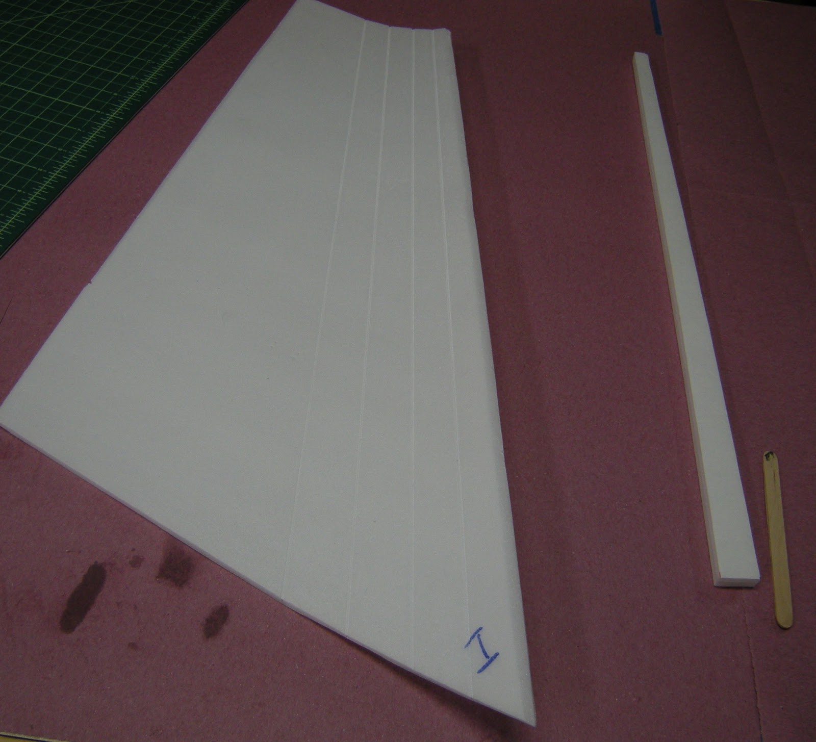
The bend points inside the wing can be scored with a popsicle stick. The score lines just need to dent the foam. There is no reason to press so hard that the foam surface is broken or cut.

The foam is gently bent until it conforms to the desired shape.

Spar Construction
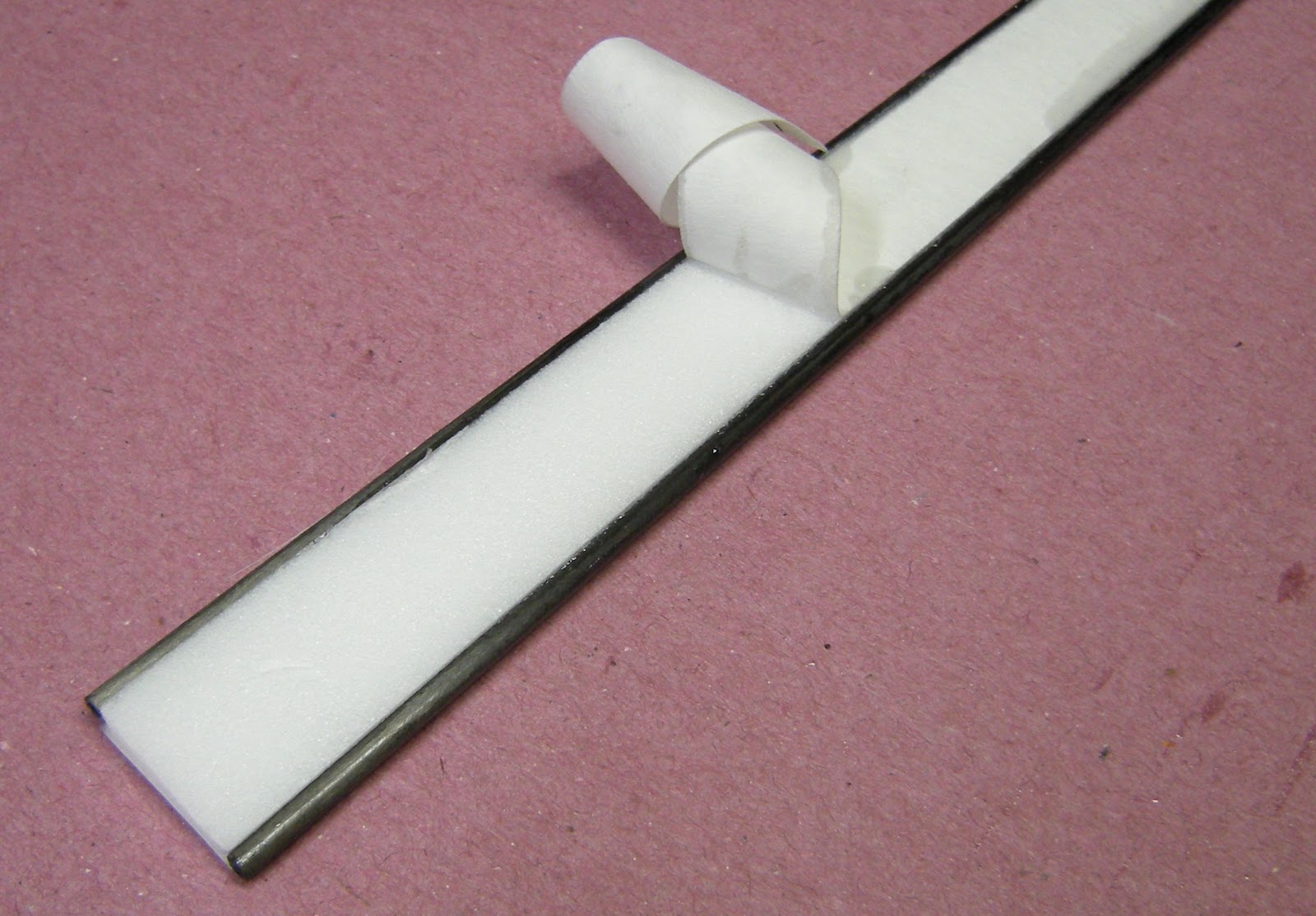
The tension put on the wing spar by upward lift causes compression forces to develop on the top edge and extension forces on the bottom edge of the spar. To create a spar that will handle the extreme forces, I designed an “I” beam with carbon fiber tubes and fiberglass.

The prototype spar was constructed by cutting Readi-Board the the length and width needed. I followed the Versa Wing spar pattern and just cut off the placement tabs. The thickness (height) of the spar was reduced by the diameter of the carbon tubes, in this case shown, 4mm (2 CF tubes at 2 mm each). The 2 mm carbon fiber tubes were glued to the foam with epoxy resin.
The paper was peeled from the Readi-Board foam.
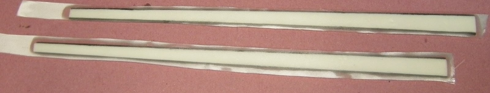
The foam and carbon tubes were overlaid with 3.14 oz/yd FG cloth and epoxy resin.
The opposite side was laid up the following day. The spars were completed by trimming the excess FG and sanding the edges. This spar design has a huge strength to weight ratio. You’ll break everything on the plane before this thing breaks.
Attaching Servos and Spar
The servos were glued onto inside surface of the top wing panel.

Someone right now is saying, “Hey, you’ve got two servos on each wing”. Yup, this V2 wing design will have rudder control surfaces on the vertical stabilizers. Don’t know if this will help, but I thought it would be something fun to try.

A line was drawn where the spar should be placed (blue - between the last and next to last score bends).
The spars were hot glued to the inside of the wing. In order to keep the glue warm during the application, the spars were first heated with a hair dryer. The hot glue was applied to the warm spar and held in place to solidify.
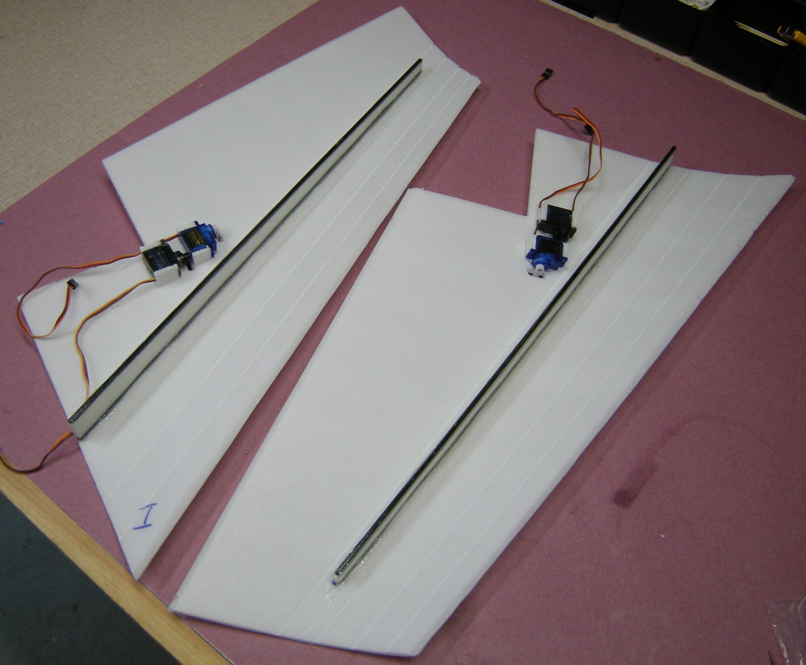
Here are both top surfaces of the wings ready to be joined with the bottom surface.
Joining the Wing Halves.There are many techniques to join pieces, this is the one I like.
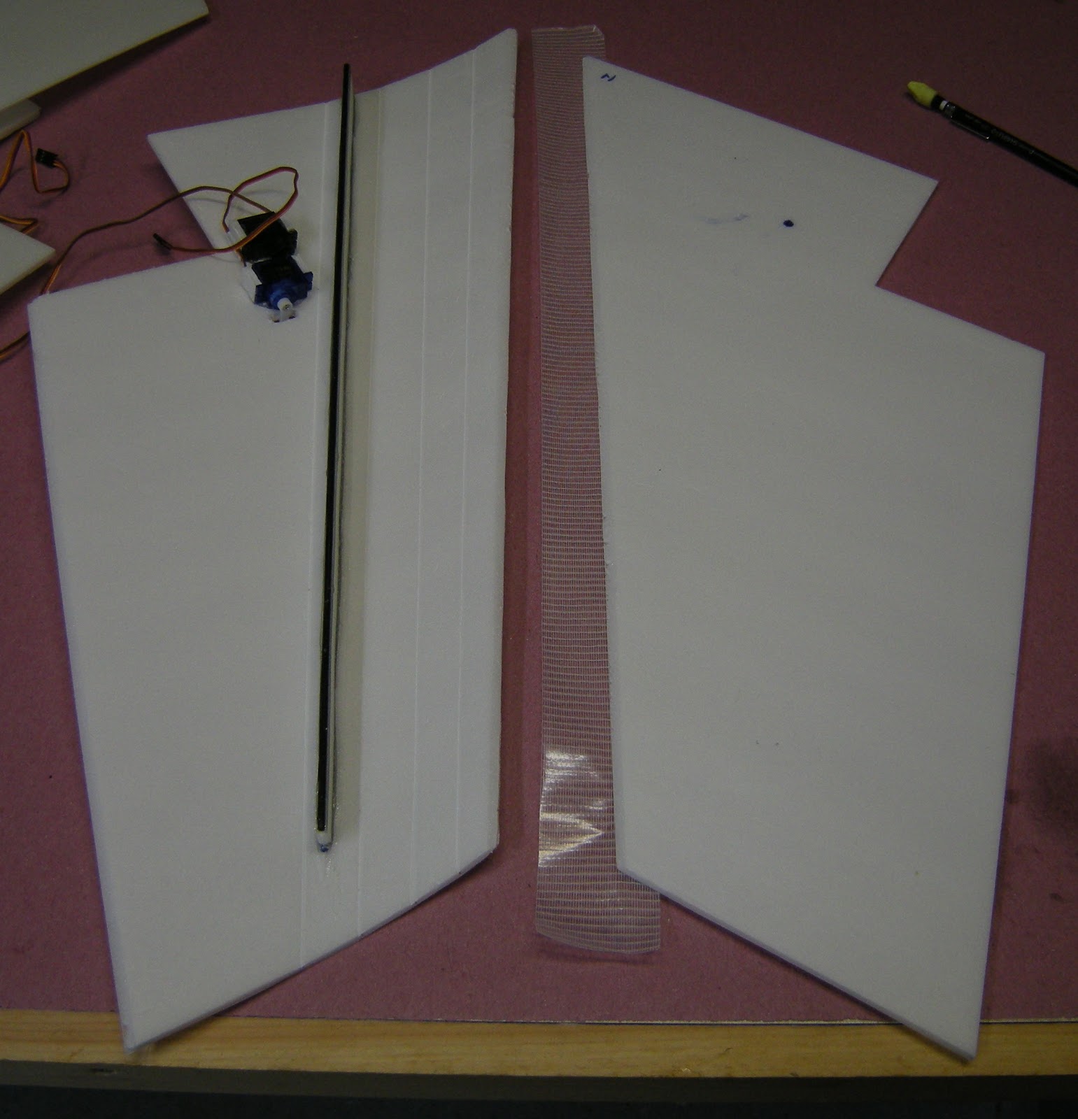
Apply tape to the leading edge of the lower wing panel.
With the bottom wing surface laying flat on the building bench with tap, the top surface is held at about 45 degrees from the bottom wing. The “V” in the double bevel leading edge match and then push the leading edge of the top wing into the tape. The tape will hold the placement of the wings pieces together. Now carefully turn the wing over and let the bottom surface overhang the edge of the table and use your fingers to press the tape more firmly into the top wing panel.

Since the paper was removed, the elevons came off too and so they had to be re-attached. They too were resurfaced in fiberglass.


They were attached at this point, but I didn’t get any pictures of the process. Here is the end result; they were attached using “X” hinges made of polyester fabric held with hot glue. This is one of the strongest hinge systems that I have constructed. They really hold well. If you’re worried about the heat of the summer melting them, the same hinge can be mounted with epoxy.
To glue the wing halves together, basically follow the Versa Wing build. Remember to warm the spar with a hair dryer so the hot glue will stay soft longer. Apply hot glue to the leading edge bevel joint and the spar. Roll the top surface over the bottom surface and hold it in place making sure the spar is touching the bottom surface foam. Joint the trailing edge by applying a bead of hot glue along the trailing edge and hold in place.

Join the two wing halves together by sanding the center edge flat, join the two wings together with tape to the bottom wing surface - making a tape hinge. Open the hinge, apply hot glue and then hold the wings together until the glue cools. Apply tape to the wing joint or run another strip of fiberglass cloth along the joint as I did.

Add the vertical stabilizers,

Add the control rods and control rod stabilizers (coffee stirrers).

Mark where the battery compartment should be

Cut the hole for the motor and battery. The motor mount was joined to the wing using one tongue depressor cut in half and some screws. The battery is secured with a loop of velcro.

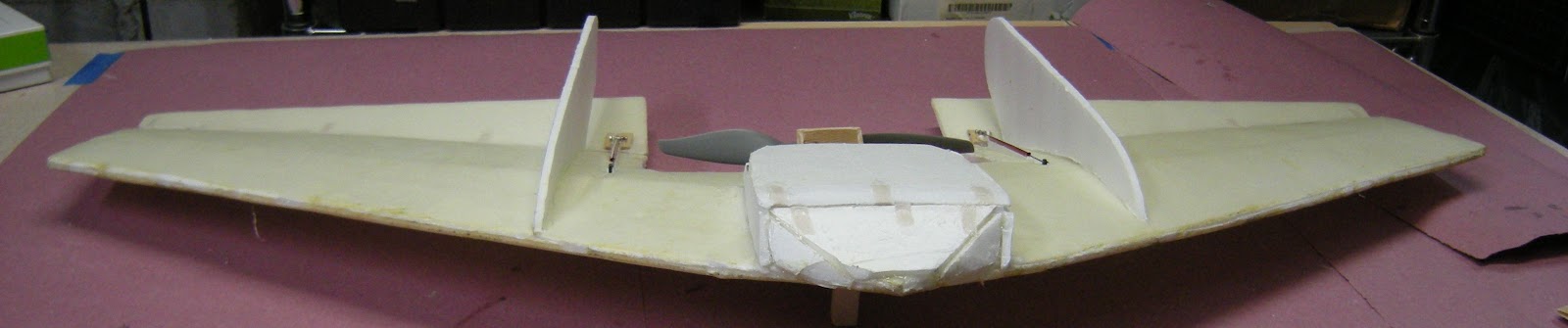
The motor mount was attached to the wing with a tongue depressor and hot glue. The battery hatch was added. The hatch was added to provide some protection to the battery in the event of an inevitable crash. I’m sure there is a better way to build a battery compartment, but here is the way I did it.

The ESC was secured inside the wing and an air scoop was added to provide cooling.


The balanced pusher Versa Wing is complete.
[video='https://www.youtube.com/watch?v=oxCFE1penJI']
Powertrain:
Delivers 26 oz static thrust at full throttle consuming 21 Amps with 3S LiPo (12.6 V).
2200 mAh battery
Turnigy D2826/10 1400kv motor
APC 8x6 prop
25A ESC
Fiberglass: Cloth from Thayercraft.com - best value anywhere http://thayercraft.com.
The epoxy resin was purchased from USComposites.com 635 Thin with medium hardener http://www.uscomposites.com/epoxy.html.
Free Plans:


Log In to reply
Log In to reply
Log In to reply
Log In to reply
Log In to reply
Log In to reply
Log In to reply
You provided very useful information in an logical and concise format- Great work.
I'm wondering what type of epoxy resin you used - (the 2-part mix or the resin w/drops of harder?) and was there any issues with the foam. I have dabbled with light FG cloth but I have used polyurethane as the "resin". I agree that the balance issue is significant (particularly for a non-FPV airframe) I am working on a scaled down version that I want to keep light. I will certainly look at doing some surgery and moving the motor forward...
Thanks-
Log In to reply
Thayercraft.com is the best deal for FG cloth that I have found. You have to buy what seems like a lot, but it is so great to use. Epoxy resin is from US Composites - the 635 Thin with medium speed hardener at http://www.uscomposites.com/epoxy.html. It is mixed at about 3:1 as specified. There are no issues with the epoxy resin melting the foam, but the polyester based resin will melt it for sure (keep it far away). Fiberglassing foam works so well, I now FG all my foam plane projects. This wing was rebuilt 3 times now. Good luck and Cheers!
Log In to reply
did you do any tests with FG over the paper on the readi board?
how about red rosin paper with polycrylic vs epoxy resin? thanks, Ed
Log In to reply
Polyester would make a nice surface and polycrylic does stiffen up. I haven't tried this combination. The cost of FG:
FG 0.73 oz/yd (Thayer Craft $0.301/sqft)
FG 1.43 oz/yd (Thayer Craft $0.168/sqft)
FG 3.15 oz/yd (Thayer Craft $0.208/sqft)
9 sqft/sqyd so FG runs about $1.80/yd - almost 2x polyester.
I did try polycrylic and paper vs. FG resin and paper combinations.
I think you'll find this article very interesting:
http://flitetest.com/articles/super-strong-waterproof-foam-core
Interesting idea, but I did not test any FG over Readi-Board paper because one of the things I dislike about Readi-Board is the paper peeling from the foam. So, I just peel the paper off and use the foam. The paper weighs a little more than the foam.
Yes - I used epoxy resin and paper. Works great!
Log In to reply
Dustin
Log In to reply
I don't know how much weight great stuff would add, but it certainly would make it stronger. If I were building a solid core wing, I'd probably go with hot wire EPS, make a cut down the middle for a spar, add carbon fiber and sheer webbing spar, glue the halves back together and glass it over.
Cheers! David
Log In to reply
Log In to reply
Log In to reply
I cut the rear notch out about 7 cm, and moved the motor forward another 3 cm. Now it balances with only 3 oz of lead. I hope it flies with the Blue Wonder!
https://i.imgur.com/okDT3OM.jpg
Log In to reply
Log In to reply
Steve, a friend in our club built a Versa Wing pusher style and used two steel plates about 1" x 2.5" in the leading edge on either side of the battery to get it to balance. Let's just say it flew sluggishly. You can see the steel panels in the front of the wing in his maiden flight:
https://www.youtube.com/watch?v=nHqYw0zwOlo&t=1s
He also got a turn at flying my Balanced Pusher Wing before his maiden, just to give him a sense of the feel.
https://www.youtube.com/watch?v=_1IA6AAIm-I
There is a world of difference with a light wing. Good Luck my friend...
Log In to reply