Hello Flite Testers !
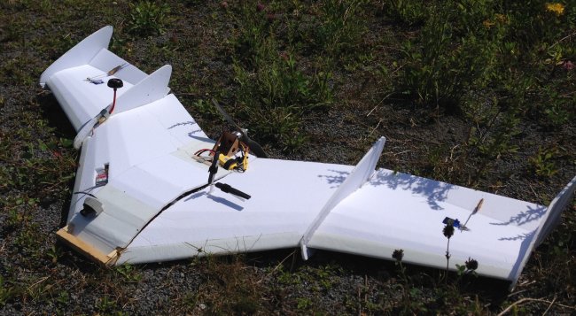
In this article I introduce my scratch-build mini-version of IBCrazy's Chimera, together with free plans and build instructions.
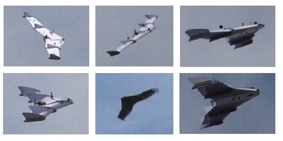
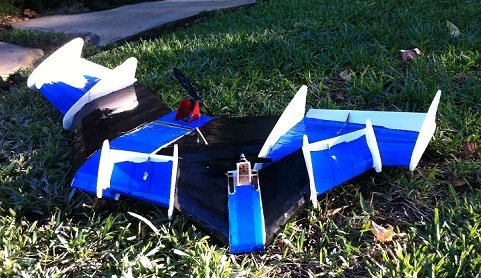
And here are few pics from Mjpilot who build this wing too, AND a micro 50% version of it!
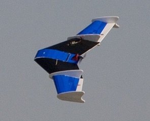
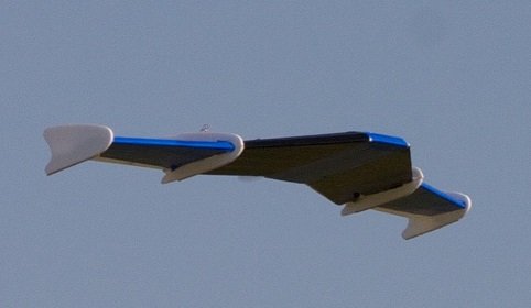
I liked the Chimera's two-panel design for the cooler and futuristic look. It has a nice silhouette in the sky, and a good aerodynamic shape. Together with that, the 2-panel design enables to have a "tall" body in the middle (fat profile), while preserving thinner wing profile at the sides. This gives a nice wide space for your FPV gear, and other electronics, which is larger then what you would have on the Blunt-Nose Versa.
So, when I run into IBCrazy's
VAS Chimera Flying Wing design, I
immediately fell in love with it, and wanted to create something similar! I looked around the web to see if there is a scratch build for that design, and found
this thread on RC groups, where wyll is presenting his scratch build mini-version of the Chimera. I had a bit of difficult time figuring out the plans there, so I decided to create the plans from scratch on the computer, based on the plans and instructions given there.
Eventually, I created this mini-Chimera scratch build design, which flies great and requires only the standard cheap FT electronics. With 2200mAH it can fly for 10-15 minutes. It has 47 inch wingspan and it fits nicely in the back seat of an average car.
The Plans
I included free plans for you to download and build. They are in accordance with the Flite Test standard for scratch build plans (black lines for cut, red for 50%, blue for crease or explanations).
I recommend building this plane after you have gained some experience building other FT kits, especially the Versa Wing and its
Blunt Nose Conversion. This is not a design for first time builders.
For you who have build the Versa Wing, you will find this build very easy, as it follows the same build techniques of the Versa Wing. To make things easy, I have tried to relay as much as possible on the
Versa build process, and I recommend to go through
that video before building this plane.
Power Set up:
Low power:
This is my original setup, it is cheap, but with full FPV gear, the climb rate won't be so amazing, and most of the time you will fly on 65% throttle, which is probablly not that efficient. With 2200mAH it flies +12 min, and with two 1300mAH in parallel will give 15-20 minutes
Battery: 3s, 2200mAH, or 2 1300mAH in parallel
Prop: 8x4 Pusher
High Power:
This setup is proposed / used by MJpilot, and it flys better as it penetrats better and has more speed. The cruise is also at a lower throttle - 50%, and it get 30+ flight time with it!
Motor: sunny sky 2216 900kv
ESC: 20A
Battery: 4s, 3000mAH
Prop: 9*4.7 Pusher
MICRO version %50 size:
Mjpilot also build a %50 size micro version of this design. The power setup he used is below: Also, he used a 3/8in square wooden dowels for spars instead of carbon fiber.
Motor: 1806 2300 kv
ESC: 10-12A
Battery: 3s, 800mAH
Prop: 5x3 Pusher
Other things you will need:
(2) 9 Gram Servos
Carbon fibre rods
Building Instructions
Before you begin, remember 2 things which are different from the Versa build:
- Do not glue the Foam-Board Spars yet! Just put them in so it will be easy to form the shape of the wing. You will need to remove them before installing the carbon fiber spars. Otherwise, the installation of the carbon fiber spars will be more complicated, as you will need to slide them through holes in the foam board spars.
- Do not close the wing panels with hot glue yet. Instead, use a duct tape to have them closed temporarily. You will need to open them when installing the carbon spars.
Building Process:
This build has 5 wing panels (in comparison to the Versa Wing which has 2):
- 2 outer panels
- 2 inner panels
- 1 middle panel
All of them are being build in the same process.
The build of each wing panel is almost identical to the Versa wing build process:
- Connect upper section and bottom section with a duct tape.
- Make a double bevel at the leading edge
- Make a double bevel on the Outer panel for the ailerons.
- Fit in the foam-board spars - do not glue them yet
- Make a 50% cut on the red lines and slightly score it.
- Slowly fold the two pieces together to create the profile.
- Add a bit of glue in the creases to add strength to the shape of the wing
Note that the inner panels meet up at the narrow side. The gap in the other side is ok.
Do not close the wing panel with hot glue yet, instead, use a duct tape to have it closed temporarily. You will need it opened when installing the carbon spars.
When you fold the wings (outer and inner) there will be an off-set of around 1cm.
The middle section should not have an off-set (by design).
In the same way, build the outer panels and the center one.
For the center panel: Use a 2200mAH battery to help shape the profile, so that the battery will fit nicely inside.
Sanding the panels
Use a sanding paper on a straight surface, to sand the sides of the 5 wing panels so they will perfectly fit each other. Same as being done in the Versa build.
Note that the shape of the fit between the outer and the inner panel does not need to be exactly 90 degrees, as long as both sides fit perfectly and compensate for each other.
The other fits (of the inner panels with the middle panel, and the outer panels with the winglets) do need to be 90 degrees.
Assembling all panels
Now, once you have all the wing panels fit each other, it is time to attach them together!
- Open the wing panels by removing the duct tape.
- You can remove the foam board spars if you want
- Glue in all the bottom parts together:
Start from the middle panel and attach the 2 inner panels on both sides (glue only the bottom part). Please check out the
FT-Racer build video (min 8:35) for a nice tip of using a tape on the working surface, and let the wings join above it, as it will function like a wax paper, and you won’t glue the wings to the work surface. If they do, release it by carefully twisting the two panels.
It might be that because of the sanding the foam board spars won't fit, this is not a problem: the carbon fiber spars are supposed to take care of strengthen the wings.
Check that when you close in the upper parts, they fit nicely together.
Glue in the second inner panel.
And check that they all fit nicely together.
Attaching the outer panels:
Attach the 2 outer panels in the same way (also, glue only the bottom part)
- Note that because the way the upper parts are folding in, the upper section of the outer panel is somewhat below the upper section of the inner panel. (See photo).
Here, checking the fit of the upper section is be a bit more tricky, as you first have to fold the upper section of the inner panel, and then the outer one.
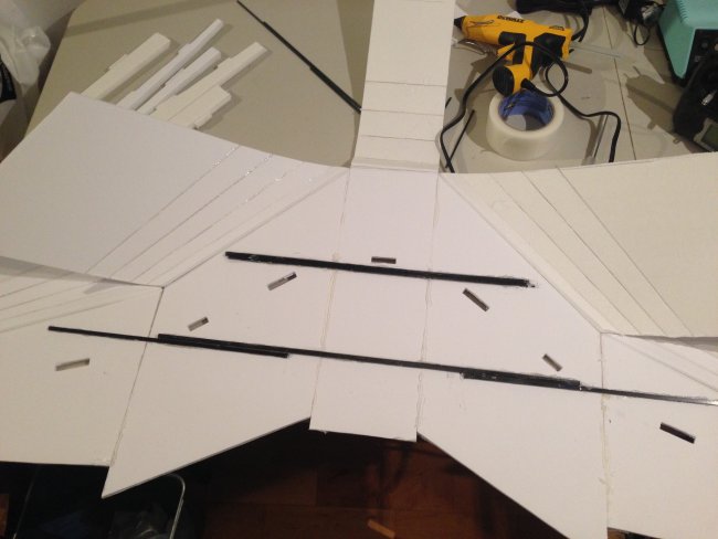
Carbon fiber spars
I installed 2 carbon spars: One long and narrow (composed out of 3), placed just a bit ahead of where the motor mount is going to be, so it will spread the load of the motor mass in case of crashing. Also it is long enough to support the outer wing panels. The second spar is shorter and thicker and supports the main body area, and together with a wood "bumper" (optional), it spreads the crash impact throughout the body.
- Remove the foam board spars
- Place the carbon fiber spars in the configuration that fits you, and glue them in.
Now, after the carbon fiber spars are installed, it is easy now to make the holes in the foam-board spars and glue them in too.
Closing the upper sections
Now everything is ready to close the wing panels, and glue in the upper sections.
- Note that we do not close the middle section as it is used as an opening hatch for now.
Start with the inner panels: Put glue on: the inner side of the leading edge, the spar, and at the connection area at the back of the wing, and close it, while checking that it fits the middle section, when it is temporarily closed. Remember: you are not gluing the middle section, it should remain to be able to open and close.
Continue with the outer panels: Close them the same way the as outer panels. This time, glue also to the upper parts of the fit.
All inner and outer panels are closed.
The middle section:
Finally, we need to deal with the middle section: The middle section will be glued only at it's rear side (where the motor is placed), but the most part of it will be used as an opening hatch.
So, first check that it fits and closes nicely. Then, put glue only at the back and on the sides only from the back till the incomplete cutting line (black) (or until where you want your cutting line to be), and close it.
Now, cut the uncompleted line, so you will have a hatch that you can open and close.
Mounting the motor firewall:
This process is identical to the blunt nose versa: cut through the lines in the middle part, to make the place for the firewall. Make sure to cut only the upper board, and just peel off the paper of the bottom board. Glue in the firewall at the location that you prefer.
When mounting the motor and the ESC, I recommend placing the ESC outside of the body, so it will have good ventilation. The ventilation inside the body is not enough and I already burned one that I placed inside.
The winglets:
The outer winglets are simply glued as they are to the sides of the outer wings, according to the marking on them.
Inner winglets:
Inner winglets has to be cut into 2 pieces each - upper part and lower part (the middle can be tossed), and to be installed separately. Those will be attached to the end of the inner panels, where they connect with the outer panels, but on the inner panel. You may need to sand it a bit in order to get a nice fit. I would recommend starting with the bottom part.
Servos:
I have located the servos far enough from the outer winglets, so it would be easy to service them, if needed. The servos should be installed flushed with the wind for minimum drag. Cut the holes for the servo, and add some cushion under it, so it will be flushed with the surface, while connected to the bottom panel from below. Do not use to much glue as the friction does its work here, and it will be easier to replace the servo when needed.
On the servo arm, I recommend to use the third hole from the centre. And on the control horn (FT control horn) to use the outer hole.
Dialing-in the linkage stoppers
Expo: 35 %
Reflex: Use a positive elevator of 15-20 degrees as a good setup for cursing around. Probably more toward the 20 degrees, so it won't dive in on launch. Still, you might need to use a lot of up trim.
A piece with 15 degrees angle is included in the plans.
Note: An option I have added, after writing this article is adding 2 small fixed pieces of foam to the back of the inner panels (see pic below), in a positive elevator of 10-15 degrees.They give the wing a constant 'up' factor, and reduce the amount of positive elevator needed from the moving elevons, thus enabeling them to work in their normal range of movement.
CG
I used
wingcgcalc to calculate the CG -
here is the calculation. I am using the 25% which came out as 24cm from the front of the airplane, and it works great for me.
Note that, according to the site, this is a 25% CG which is for experts. If you feel less comfortable with this, check the site for other values.
Another Note: MJpilot reported using 1/4 in behind, which is around 25.65cm.
Possible arrangement of electronics:
There is a wide space for various electronics inside the middle section. Here, I have 2 1300mAH in parallel, Turnigy T1000 AutoPilot, Receiver, and still left with room for more stuff.
I hope to check in the future how a bigger Auto Pilot like the Vector will fit here.
Optional Additions
FPV transmitter and antenna:
I created a niche inside the wing for the FPV Tx, so it is well ventilated and flushed against the wing surface.
The antenna is connected through a coax cable and exit next to the inner winglets. That way, if the antenna gets hit when crashing (and it will get hit, because you want the antenna to be located high), the FPV transmitter plug will not break. The coax cable will absorb the bent.
Front Bumper:
I am using a 'front bumper' because during testing I crashed it a lot. The bumper shifts the hit backwards into the front carbon spar, which spreads the hit across the body. This helps to prevent the nose from deforming, and protects the batteries and electronics. All it needs is a simple H like wooden boom that comes out in the front. There is no need to glue it very strong, because you do want to take it off, once you are feeling ok with lunching and flying the air plane.
Conclusions
Designing and building this plane was a long but very rewarding process for me. I have learned a lot about the process and discovered that it takes a lot of work: drawing the plans, print them, cut and build, make changes, redraw the plans, cut and build again... then you have to take care of the CG calculation, check that it flies well. And also make the build process simple enough and recording everything in the build process so it will be easy for others (you guys) to build it too.
Lucky me, I have a copy store next to my house, so I could reprint the design on a large sheet of paper very easily. But I did had to cut the boards by myself each time. I hope that I could find a service that can laser cut it for me; that would speed up the process very much.
Another exciting part of having a design in the computer, is that you change it very easily. For
example, if you want the model to have a wider middle section, or longer wing span. Another option that I am
planning, is to play more with the
dimensions of the wing panels, in order to create a model of the Northrop Grumman
B-2, or
X-47B, as both of them have the basic design of a 2-panel flying wing.
I hope you liked this article, and that you will build and fly this airplane, and of course, I would be happy to see pictures and videos of your builds!


Log In to reply
Log In to reply
it looks like my next build, as soon as I get some free time on my hand.
Log In to reply
I did 3 builds, and the plans are according to the 3rd one. The pictures are a mix of the 2nd and 3rd build, that's why in some of them it looks a bit worn out :-)
Log In to reply
Log In to reply
Please update us how it went.
Don't forget 15 degs, and have some expo, like 30% is ok.
Good luck ;-)
Log In to reply
Log In to reply
Log In to reply
Log In to reply
Mjpilot
Log In to reply
And sorry for the first 2 trials...
Well done for the persistence, and for flying it! Chapeau
What was the final expo and ailerons angle that you used? And CG?
Log In to reply
Log In to reply
Having your CG a bit backward, means that you have more weight at the back, so the plane should have been pulling up anyway, and you still need 20 degrees and not 15, plus you have a lot of up trim...
I guess every build is a bit different, the location and angle of the motor and such.
The only thing I might think is worth trying is to try to bring the angle to 15 degrees without any up trim, as it would make the plane more efficient. You can do this by moving more weight to the back, hence moving the CG more backwards.
Please let me know how it went, and post some pics ;-)
Log In to reply
For anyone wondering, I am using a eflite park 370, two 9g servos, 2400 3s, 9*4.7 prop, and a 40 amp esc.
Log In to reply
This design doesn't have that, so a lot of "up" is necessary, considering that the control surface is small and has to compensate for the part of the wing without.
I wonder if I will make some addition to the inner wings, if that would help. Another option is to design a wing with a shorter upper section and not button section. When folding, it will give the nessesary reflex. Have to try that...
You can send the pictures to: talsharf@gmail.com and I will try to add them to the article, together with other information that you have posted.
Cheers,
Tal
Log In to reply
Log In to reply
Log In to reply
Log In to reply
Log In to reply
Log In to reply
Log In to reply
Log In to reply
Log In to reply
Log In to reply
Yea, it took me time to do it, but the learning process was very rewarding. Now I even use a 3D software (Scketchup) to make the 3D model, and from there I do 'unfolding' to the final plans.
Log In to reply
I will try to build a "mighty mini" with a 250er size quad motor
Log In to reply
Update us how it is going, it should be very interesting to see a mini version of it!
Log In to reply
1. get the newest version of adobe acrobat reader
2. when printing, go to page sizing and handling, and select poster
3. set tile scale to 100%
4. print and use as if it were tiled plans
Log In to reply
https://www.jottacloud.com/p/penthane/c172e926246d47e18acf92a153265b2d
https://www.jottacloud.com/p/penthane/1c663edcf5cf40998ad8b712b5bbcf18
https://www.jottacloud.com/p/penthane/2f31d306028f4d32a5006631cafeb20c
https://www.jottacloud.com/p/penthane/f0a425d392094f80a7eb14c9be5f4b85
Span 1.40m, detachable wings for transport. Total weight (incl.batt) 1050gr.
Spars of aluminium.
Foam: Depron-like 5mm
2x XA2212 (abt. 2x 800gr thrust).
Battery: LIPO 3s 30C 4000mAH with spare room for 2x 2200mAH
Flight control: CC3D (I'm a terrible pilot)
Wanted to show it before first landing ;) I'll let you all know how it flew later.
Log In to reply
Log In to reply