APM:Copter Flight Mode Setup with the Taranis X9D
June 2015 - HilldaFlyer
Program the Taranis X9D Plus to select 7 APM flight modes on the APM:Copter with voice announcements.
![]()
Abstract
This article will demonstrate a couple of ways the Taranis X9D Plus can be programmed to provide 7 flight modes for the APM:Copter. Other information in this article that you may find useful is the addition of voice announcements and a volume control slider.
Introduction
This past winter I invested in a new transmitter. After weeks of research and reading discussion boards I settled on getting a Taranis Plus for a few reasons including flexibility in programming and low cost to function/feature ratio. I was really attracted to the Taranis because the of the flexibility it offered in letting the pilot chose which switches go to which channels. In a nutshell, you can adjust the transmitter’s logic to match your own. Because of this rich feature set, I discovered that there is a bit of a learning curve to be overcome. However, once understood, programming is straightforward.
It was my experience that programming the Taranis for a basic airplanes and multicopters was pretty easy, including programming dual rate and expos, and elevons for flying wings. I worked through the OpenTX University (http://open-txu.org/) that provided me with a concrete foundation in the logic. However, I found that programming the flight modes for my APM flight controller proved to test my beginner abilities to the open source logic. I started searching for help and tutorials to guide me through the process of programming the Taranis to provide 6 flight modes. I found a few posts, but truth be told, the first one I came across I did not understand. I kept telling myself that it should be easy to be understood. So, I set out on my own and this is article is the outcome of the path less travelled. The purpose of this article is to provide the information on how I programmed the Taranis to give 6 (or 7) flight modes for the APM flight controller. In addition, at the end of the article I will provide links to information available on several sites and videos that I found in my quest.
Decide which switches to select the flight modes.
Most transmitters that I am familiar with don’t have a built-in 6 position switch. If you’re does, great!, you can stop reading here and go back to the reading the owner’s manual. Many of the higher-end transmitters have a variable pot. Yes, you can use a multivariable pot or slider, but I imagine it is pretty hard to adjust it to a defined value without defined clicks or positions, especially while flying and most especially if operating in a panicked mode.
Installing a single 6 positions switch
Here I list several links to posts detailing how to modify transmitters by installing a 6 position potentiometer so that all flight mode channels could be selected on one dial.
https://www.youtube.com/watch?v=Ts0EzeJsoNc
http://diydrones.com/profiles/blogs/new-taranis-6-position-switch
http://diydrones.com/profiles/blogs/6-position-mode-switch-for-apm
Using two switches to create 6 PWM values
Most RC pilots will default to selecting the flight modes using the combination of two switches. The task of generating 6 different pulse width modulation (PWM) values can be easily accomplished using a combination of 2 switches, either one switch with two positions in combination with another three position switch or two switches with three positions each.
I decided to use two switches with three positions each (SD and SG) on my transmitter, for no other reason than the Tarnis only has one switch with only two positions (SF) and I use switches SE, SA and SB for other functions like controlling flaps, dual rate and expo on other models. I thought that physical separation of switches and function would prevent me from getting confused and mixing them up while flying.
Defining Logical Switches
With the practically infinite functionality of the Taranis, there are multiple ways of reaching the desired outcome. I found that creating logical switches the easiest for me to understand and very straightforward. The semi-tricky part to this procedure is to understand that the transmitter uses pulse width modulation (PWM) to communicate with the receiver but the transmitter setup screens use weight % (percent throw/tavel) to communicate with the operator.
Lets start by defining the positions of the two switches to produce a combination of 6 outcomes. The path of information flow I used was to create 6 different logical switches that are defined by the position of two physical switches. I then used the mixing to define the % weight for each of the 6 logical switches. First things first, the goal is to create 6 PWM values from two switches. For the sake of defining direction, I will use forward (fwd arrow up) to refer to the switch toggled away from the operator, middle (mid) to be centered and back when the switch is toggled toward the operator (arrow down).

Screenshot from OpenTX Companion showing the definition of the logical switches. Because I chose to use two switches with three positions each (which have a total combination of nine outcomes), the outcome for one switch would be limited to two positions. To accomplish this, I used the logic SD(fwd) and NOT SD(Fwd)(!SD(fwd)) to limit the three positions to two, fwd or not fwd.
The next step is to get each logical switch to produce a defined PWM value. Pulse widths ranges for each flight mode are defined by APM:Copter (http://copter.ardupilot.com/wiki/common-six-modes/). The PWM ranges for each of the 6 flight modes on channel 5.
FM 1 – PWM <1230
FM 2 – PWM 1231 - 1360
FM 3 – PWM 1361 - 1490
FM 4 – PWM 1491 - 1620
FM 5 – PWM 1621 - 1749
FM 6 – PWM >1750
This means that our logical switches should be defined to produce the PWM values somewhere in the specified ranges.These ranges that center on: 1165, 1295, 1425, 1555, 1685 and 1815 microseconds. If you know the ratio of PWM Values (microseconds pulse width) per weight % of the transmitter, then the weight % output can be deduced/derived through arithmetic. The first step is to know the PWM values of your transmitter at -100% and 100% weight. The PWM values can be determined through the APM Mission Planner Radio Calibration tab.
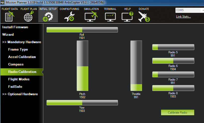

Channel 5 showed a PWM Value of 991 microseconds at -100% (both switches forward).

At 100% (both switches back) it was 2015 microseconds. The calculation resulted 5.1 microseconds / weight %. Therefore, to get from the starting 991 value at -100% to the middle of the next range at 1295, the PWM value needs to increase by 300 microseconds which equates to 59% weight in the transmitter output. Adding 59% to the starting value of -100% we arrive at the target % Weight of -41%. Next target - to get the PWM value from 1295 to 1425, the PWM value needs to increase by 130 or by 25% weight making the next target weight -16%. I used a table to perform the calculations.
|
PW |
PW |
Target PW |
PW increase to next target |
Target Weight % |
||
|
FM 1 |
991 |
- |
1230 |
<1230 |
-100 |
|
|
FM 2 |
1231 |
- |
1360 |
1295 |
59 |
-41 |
|
FM 3 |
1361 |
- |
1490 |
1425 |
25 |
-16 |
|
FM 4 |
1491 |
- |
1620 |
1555 |
25 |
10 |
|
FM 5 |
1621 |
- |
1749 |
1685 |
25 |
36 |
|
FM 6 |
1750 |
- |
2015 |
>1750 |
100 |
This table shows the PWM ranges defined by APM for the 6 flight modes and the calculation to percent throw. Now that we’re through with the math, we just need to use the mixing tab to define each logical switch with the set target weight % and then demonstrate that our calculations were right.
Mixing the Logical Switches to produce 6 PWM Values
The mixer tab is the place to define the % weight for each logical switch. I used MAX source and then % weight as defined in the table above.

This is a screenshot of OpenTx Companion Mixer Tab with the values used for channel 5. You will notice that I added a half second delay to each of the mixes. This was unnecessary but it provides a slight delay so I have a split second to observe the change in flight modes. With the above % weights locked in, I measured the PWM values that were actually received by the APM.
|
PW |
PW |
Target PW |
Values Achieved |
||
|
FM 1 |
991 |
- |
1230 |
<1230 |
991 |
|
FM 2 |
1231 |
- |
1360 |
1296 |
1293 |
|
FM 3 |
1361 |
- |
1490 |
1426 |
1421 |
|
FM 4 |
1491 |
- |
1620 |
1556 |
1555 |
|
FM 5 |
1621 |
- |
1749 |
1685 |
1683 |
|
FM 6 |
1750 |
- |
2015 |
>1750 |
2015 |
I’d say that was a success. The target values were hit every time. A change of 1% weight leads to a 5 micro seconds PWM change, so these could be adjusted a bit if one wanted to do that. You now have 6 different PWM values going to your receiver on channel 5. Congratulations… Do you want to get cool? then add some voice announcements.
Adding Voice Announcements.
You can personalize any of the 6 flight modes for your use. I added voice to the flight modes so that the Taranis will tell me which flight mode I switched to without looking down away from my copter.

Screenshot of the special functions that play tracks of voice when the switch is activated. By the way, I added Special Function 8 which (SF8) which makes knob S2 control the volume of the speaker.

My home-built FormicaQuad in loiter mode.
Programming 7 APM Flight Modes
But wait… there’s more. That’s right, to this point only 6 flight modes are programmed which correspond the 6 modes that can be assigned on channel 5 on the flight mode tab of the APM:Copter. Is it really true that you can get 7 flight modes? Yes, it is true, you can program 7 flight modes, but the seventh should be considered as the one flight mode to rule them all. It is programmed to a different channel, in my case channel 7. This setup is performed in a different place than where the 6 flight modes are defined. I learned this cool trick from blogs, tutorials and Youtube videos that I found while searching for “Taranis APM Flight Modes.”
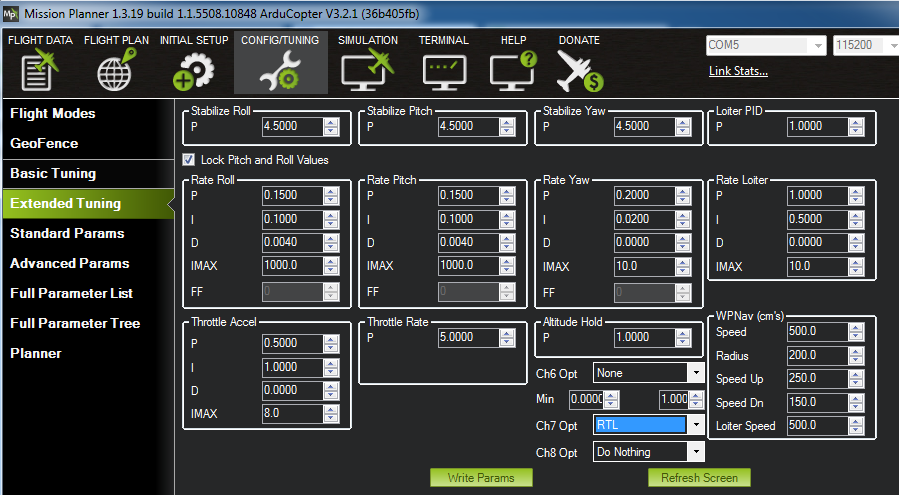
Channels 7 and 8 can be programmed to perform a variety of functions for AMP:Copter in the Extended Tuning tab of Mission Planner. The one flight mode to rule them all is programmed on the APM as channel 7 (in blue) as shown. In the dropdown menu, just select what you want channel 7 to do. I selected this to be return to launch (RTL). If I get in trouble while flying in one of the other flight modes, I only have one switch to toggle and if all works right, my model will come back to me. Think of it as a panic switch.
Interestingly, Mission Planner indicates that flight mode 1 (Stabilize highlighted in green) is selected even though channel 7 was activated and the current flight mode is RTL.
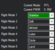
In the example above, the Stabilize mode (both SD and SG switches up) is selected, but I’ve toggled channel seven (switch SF back) so RLT is the last action.
With this setup, I noticed that if RLT (switch SF) was toggled to inactivate RLT, it should return to one of the six flying modes - but since the logical switch was already active, the voice announcement did not happen. To get the voice announcement of the flight mode when cancelling the RTF, I included the SF switch in the logic for selecting the Logical Switch 1 through 6.
Screenshot of Logical Switches used to select the 6 flight modes showing the addition of the SF switch (AND Switch column) to the logic. There are a couple of benefit in using this scheme.
- The logical switches will only be activated when the SF is toggled to the forward position. In other words, as long as SF is in RLT, the other flight modes are inactive. Previously, if one of the switches were bumped, RTL would be toggled off and the bumped switch would dictate the flight mode.
- When RLT is deactivated, the flight mode is returned to the logical switch and the voice announcement is made.
- When RLT is activated, the logical switch on channel 5 becomes inactive and returns a value of 0% weight, which is within the range for flight mode 4 (Loiter mode for this setup)
What I find very satisfying with this scheme is that the SD and SG switches can be toggled into any positions while channel 7 is active (SF back) to prepare for what mode you want to return to when channel 7 is inactivated. For example, you’re flying around in drift mode and lose orientation. Flip the switch to RLT and wait for it to return close enough to regain orientation. If you don’t want to resume the drift mode, toggle the switches to another flight mode, like altitude hold or loiter mode and then deactivate RLT.
Conclusion
Being relatively new to the Taranis logic, I can’t say with any degree of certainty that all the steps above are necessary or warranted. All I know is that I understood the logic and programming, plus, it worked to produce 7 flight modes with voice announcements. If you have a suggestion, please leave a comment to help us all learn.
Alternatives..
Like I said before, there are more than one way to achieve the same result (I was going to say, skin a cat, but I didn’t want to offend any cat lovers out there). After thinking about it for a minute or two, I devised a way of producing the 6 flight modes without creating logical switches. So, if you don’t like the idea of using logical switches, below are some suggested settings that will produce the 6 flight modes. The logic is to create equally spaced PWM Values so that each new step is just an addition to the one above it.

Screenshot of the OpenTX Companion Mixes tab showing entries to produce 6 flight modes for APM:Copter using only mixed physical switches (no logical switches programmed). In this setup we are not starting at -100% weight, but somewhere in the middle of the range. The first three steps incrementally deliver increasingly larger % Weights. The last entry offsets the entries above it by 65% and then adds 11% resulting in the following outcomes.
|
Switch Setting |
Target Weight % |
Achieved Weight % |
|
SD (fwd) & SG (fwd) |
-65 |
-64.8 |
|
SD (fwd) & SG (Mid) |
-41 |
-41.0 |
|
SD (fwd) & SG (back) |
-15 |
-14.8 |
|
SD (mid) & SG (fwd) |
10 |
11.1 |
|
SD (mid) & SG (mid) |
36 |
34.0 |
|
SD (mid) & SG (back) |
61 |
61.1 |
Utilizing this scheme the flight modes will be entered into Mission Planner in the order of
FM1 - SD(fwd) & SG(fwd)
FM2 - SD(fwd) & SG(mid)
FM3 - SD(fwd) & SG(back)
FM6 - SD(mid) & SG(fwd)
FM5 - SD(mid) & SG(mid)
FM4 - SD(mid) & SG(back)
With this alternative setup, here are the PWM Values of the AMP:Copter
|
PW |
PW |
Target PW |
Switch Setting |
Target Weight % |
Achieved Weight % |
Ideal settings APM:Copter |
PWM Values Achieved |
||
|
FM 1 |
991 |
- |
1230 |
1166 |
SD (fwd) & SG (fwd) |
-65 |
-64.8 |
1165 |
1171 |
|
FM 2 |
1231 |
- |
1360 |
1296 |
SD (fwd) & SG (mid) |
-41 |
-41.0 |
1295 |
1293 |
|
FM 3 |
1361 |
- |
1490 |
1426 |
SD (fwd) & SG (back) |
-15 |
-14.8 |
1425 |
1428 |
|
FM 4 |
1491 |
- |
1620 |
1556 |
SD (mid) & SG (fwd) |
10 |
11.1 |
1555 |
1560 |
|
FM 5 |
1621 |
- |
1749 |
1685 |
SD (mid) & SG (mid) |
36 |
34.0 |
1685 |
1682 |
|
FM 6 |
1750 |
- |
2015 |
1815 |
SD (mid) & SG (back) |
61 |
61.1 |
1815 |
1816 |
The PWM Values are almost right on dead center of the ranges. For me, it was a little more difficult to get to the end result, but possible.
References
As indicated earlier, here links are a couple of setups that makes sense to me.
http://diydrones.com/forum/topics/how-to-program-the-frsky-taranis-for-apm-6ch
http://ardupilot.com/forum/viewtopic.php?f=10&t=4638
The links to the last setup is one that I cannot understand and it seems to be one of the preeminent hits on the web and keeps coming up over and over when searching. I have not tried it, so I suppose it works because it is referenced in different forums. If anyone want to take a crack at explaining it to me so I can understand the logic, I’d like the learn - thanks.
http://diydrones.com/profiles/blogs/frsky-taranis-setup-6-flight-modes-plus-1-for-apm-ardupilot
http://openrcforums.com/forum/viewtopic.php?f=96&t=3924
https://www.youtube.com/watch?v=KBISRi4NEO8


Log In to reply
2015 us (at 100% stick) to 991 us (at -100% stick) = 1024 us range from -100% to +100%.
1024 us range divided by the 200% range (-100% to 0 to 100%) = 5.12 us per %. Using this will allow you to back calculate the steps needed to hit all the steps in the range.
Log In to reply
http://tro.pe/22MISwS
Log In to reply
Log In to reply